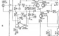
Does anybody know the purpose IC602 op amp that is shown in the attached picture? The channel output is fed back from the right via R614 to the input diff amp, but also via R688 to the input of this op amp. The op amp output is driving the input of the diff amp.
??
??
Attachments
Perhaps Bob means what does it actually do...
and its function is to maintain the speaker output at almost exactly 0.00 volts DC, in other words active control of DC offset.
Look at it purely in DC terms. The opamps non inverting input is tied to ground via a 4.7 meg resistor. The inverting input connects to the speaker output.
Remembering the golden rule of opamps which is:
An opamp with feedback will do whatever is necessary to bring the voltage difference between the two inputs to zero.
means that the opamp output will alter its value to bias the main audio amplifier so that the output (which is the point being sampled) is at zero volts DC.
If we applied a known voltage to the non inverting input (which is currently tied to ground) then the speaker output would bias up to that same applied voltage... and so keep good the rule of keeping the voltage difference at zero between the opamp inputs.
Yes Mooly but I am not a fan of DC servos , good in their place but that place at the input ( most sensitive position) would only have justification if there was no series capacitor to block DC and C602 exists .
Sure I see the practical point ( up to a point ) I usually come across them just after the input devices but I would like your opinion on this chaps critical statement and could you point out where he is "wrong " in an engineering sense.-
DC Servos
Sure I see the practical point ( up to a point ) I usually come across them just after the input devices but I would like your opinion on this chaps critical statement and could you point out where he is "wrong " in an engineering sense.-
DC Servos
I'm not really following where your going here...
C602 is just the standard input coupling cap. The DC servo is there to bring the offset down to essentially zero and could be as much a marketing decision as anything else.
Having a servo with a DC coupled input stage would be very bad practice because the servo would be trying to do something it shouldn't and that is to then force a zero voltage at the output in the presence on an input voltage.
If you look at the component values here you can see the servo is pretty 'light' in its action due to R606.
I can't recall reading that article of Rod's before but very quickly skimming through and he seems to have the same thoughts as myself such as source impedance of driving stages and that being a problem to apply correction at that point if its a low impedance node etc.
Has he said something in error in the article?
No Mooly as far as I am concerned he hasn't said something in error and I do agree its more a marketing decision but out of all the power amp designs I have come across in EW from the 70,s to the early 2000,s not one had a servo at the input and some of the audio designers were very well known worldwide.
I think back in the 70's and 80's it was generally accepted that an offset of -/+0.1 volts was acceptable which is pretty easy to achieve in most designs. Then ever lower offset became fashionable.
Same with soft start circuitry. We managed perfectly well for decades without it and now everyone wants soft start and frets over inrush currents.
Same with soft start circuitry. We managed perfectly well for decades without it and now everyone wants soft start and frets over inrush currents.
Ignoring the input voltage which should be zero because of cap 602, there is another reason to maintain the centerline at zero. If the centerline creeps off the middle, clipping happens more on one side of the output waveform than the other. The side that has a dc bias to it, that side clips first. Clipping of course causes large harmonic distortion, which is a quoted spec at full power.
If the purchasing dept doesn't buy vas or drivers well matched or something, the amp may tend to drift off center. Well matched parts cost money because that was a hand sorting process long ago. So this op amp may be cheaper than matched parts at the time this amp was made. Centering the output pushed max watts @ x% hd up as far as possible, which sold more amps.
If the purchasing dept doesn't buy vas or drivers well matched or something, the amp may tend to drift off center. Well matched parts cost money because that was a hand sorting process long ago. So this op amp may be cheaper than matched parts at the time this amp was made. Centering the output pushed max watts @ x% hd up as far as possible, which sold more amps.
Last edited:
Its called a DC servo and as said previously maintains zero output DC offset.
They work very well and make up for drift in Vbe multipliers and other components.
They work very well and make up for drift in Vbe multipliers and other components.
I think we are at cross purposes Nigel its not what it does theoretically on circuit function but its effect on the signal which is more than it would be if it was after the first stage as most of the circuits I have seen.
No Mooly as far as I am concerned he hasn't said something in error and I do agree its more a marketing decision but out of all the power amp designs I have come across in EW from the 70,s to the early 2000,s not one had a servo at the input and some of the audio designers were very well known worldwide.
You must have missed my article in the February 1996 issue then. QUAD also use these loops in some of their amplifiers.
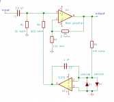
By the way, I don't agree with Rod Elliott's statement about inverting DC loops. When you know how to calculate a transfer function, it is easy to design a DC loop like this such that it gives a nice second-order Butterworth high-pass response when driven from a low impedance and something that is more damped when driven from a resistive or capacitive or something in between source.
The (simplified) schematic shows my variant, designed to have a second-order Butterworth high-pass response at about 1 Hz when driven from a low impedance and something a bit more damped when driven from a resistive or capacitive or something in between source.
Attachments
Last edited:
I think back in the 70's and 80's it was generally accepted that an offset of -/+0.1 volts was acceptable which is pretty easy to achieve in most designs. Then ever lower offset became fashionable.
Same with soft start circuitry. We managed perfectly well for decades without it and now everyone wants soft start and frets over inrush currents.
Back in the tube days those offset numbers were even better.😛
I looked up your article Marcel ,the difference is the circuit shown on this thread has both in/out of the IC before the first stage yours has only one part of the IC at the input side .
I like your rebuttal to D.Self as regards the "weak inversion area " although I do side with JLH in his use and "gentlemanly" backing for mosfets as compared to the heavy criticism he was up against --I still think it was unfair.
I like your rebuttal to D.Self as regards the "weak inversion area " although I do side with JLH in his use and "gentlemanly" backing for mosfets as compared to the heavy criticism he was up against --I still think it was unfair.
Actually it isn't clear from the schematic fragment of the opening post, but I assume that R614 is the main feedback resistor and the DC loop is driven from the amplifier's output. Node E12 appears to be some sort of input signal ground, connected to the main ground via R610 and C606.
Driving and controlling at the input would mean you just emulate an inductor to ground, which would indeed be a bit silly.
Driving and controlling at the input would mean you just emulate an inductor to ground, which would indeed be a bit silly.
The advantage here (and in MarcelvdG's plan) is that the input pair may be run at quite high current, yet with large base resistors, without trouble from base current offset errors.
Look at the top one. The right side biases as zero, but the left side has the servo at +5V! Which divides-down to 3mV at the base, which is about the error we expect from the base resistor unbalance.
The idea that clipping offset is the reason fails when you figure the worst-case output offset is maybe 1V (50mV error times DC gain of 20) and for supplies over say +/-12V that's insignificant.
- Home
- Amplifiers
- Solid State
- Adcom GFA-545II - what's this op amp do?