I fried the left channel of a fairly new to me ($100 craigslist) Adcom GFA-4300.
The service manual I found online has pages 1-6 out of 8. Would like the missing pages!
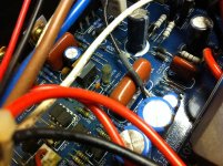
Opened the chassis the next day and noticed 2 or 3 of the 4 power supply caps are bulged and possibly leaking something which burns the nose. It's on the way to the garage until I decide what to do.
The fuse at M001 was blown. I'm not rushing to the store to replace it.
White output wire shown in the photograph is now yellow for the left channel, as in burnt color. The right channel is still white.
Anything besides the PSU caps which may be suspect?
Upgrades for quality?
It is slightly underpowered for my low efficiency 4 ohm speakers but I think it will do. Don't get me wrong, it has enough power to make me want to leave the room for most music but some albums make the distortion alert lights flicker a little when loud. In other words, it will be used hard from time to time. Sounded good until the incident.

The service manual I found online has pages 1-6 out of 8. Would like the missing pages!
Opened the chassis the next day and noticed 2 or 3 of the 4 power supply caps are bulged and possibly leaking something which burns the nose. It's on the way to the garage until I decide what to do.
The fuse at M001 was blown. I'm not rushing to the store to replace it.
White output wire shown in the photograph is now yellow for the left channel, as in burnt color. The right channel is still white.
Anything besides the PSU caps which may be suspect?
Upgrades for quality?
It is slightly underpowered for my low efficiency 4 ohm speakers but I think it will do. Don't get me wrong, it has enough power to make me want to leave the room for most music but some albums make the distortion alert lights flicker a little when loud. In other words, it will be used hard from time to time. Sounded good until the incident.
Attachments

If you've smoked a speaker output wire then I would think that certainly one or both of the output mosfets are shorted in that channel. No other components are burnt? How about any of the drain resistors?
Page 7 sure would be handy.
I haven't figured out which are the drain resistors, but so far the resistors in proximity to the burnt wire are testing the same on both channels.
I think this takes the place of page 8 of the manual...
http://www.diyaudio.com/forums/attachment.php?attachmentid=462181&stc=1&d=1422493622
I hope I don't jinx myself, but I'm surprised at how easy they made this to work on - looks like I can almost completely simply unplug the power supply from the rest of the system - and get the leaking capacitors away from my nose and eyes.
... NO, the person that assembled it didn't heat shrink or solder the connections from the power supply to the left and right channels, but the connections from the transformer are soldered in... wonder if a loose connection could have been part of the issue. At least I can flip the power supply board upside down without unsoldering the tranny and remove the leaking caps.
Attachments
Just from the one limited view you posted I can tell that some work has been done in the past. If one of the speaker wires is burnt and Fuse M001 is blown I would expect Q013 or Q015 or maybe both to be shorted. The big question is how did it develop enough current to burn the speaker wire which is at least an 18 ga wire without first opening the fuse or smoking a trace on the board. What was the blown fuse at M001 rated for? Was it 4A like the schematic shows?
thanks for looking.
yes, 4A
and it might be 16 gauge wire
how can it be determined if Q013/15 are shorted? simply order matched replacements of IRFP240's or all around? I can clean the boards up, replace the fuse. Maybe the left channel and heatsink will be removable easily and I can check the underside of the board.
Don't know if it makes a difference but the IRFP240's and IRFP9240's appear to have have different mfg markings. maybe it was the norm when then moved production to china.
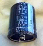
here is a photo of the caps on the left channel. similar condition to right channel. was it normal to mix mfg.'s of caps? I can't read who made the blue ones, but some are not exactly even along the scoring lines at the top as shown in the cap at the bottom of the photo. The nichicon caps are still flat - except for the ones that were pulled from the power supply, 2 were happily bloated and leaking.
weird how the power supply to left and right channel connections were never soldered or heat shrinked. no solder on the terminals.
not sure how much to put into this.

yes, 4A
and it might be 16 gauge wire
how can it be determined if Q013/15 are shorted? simply order matched replacements of IRFP240's or all around? I can clean the boards up, replace the fuse. Maybe the left channel and heatsink will be removable easily and I can check the underside of the board.
Don't know if it makes a difference but the IRFP240's and IRFP9240's appear to have have different mfg markings. maybe it was the norm when then moved production to china.
here is a photo of the caps on the left channel. similar condition to right channel. was it normal to mix mfg.'s of caps? I can't read who made the blue ones, but some are not exactly even along the scoring lines at the top as shown in the cap at the bottom of the photo. The nichicon caps are still flat - except for the ones that were pulled from the power supply, 2 were happily bloated and leaking.
weird how the power supply to left and right channel connections were never soldered or heat shrinked. no solder on the terminals.
not sure how much to put into this.
Attachments
upgrade for this Nichicon ps cap? 10000uf 63v?
I can't find an exact match for this part, but several close.
I see more LS types than LK, not sure what those refer to.
Just want to make sure I'm not ordering something that has equal or lower performance.
It's 35x40 in size, estimate tabs to be 10mm. Not limited in space for more height.
Not trying to waste money, but don't want a do it yourself for no improvement in sound quality project. I have to replace these before I can test the IRFP240's... and for now testing simply means do they work. Not ready to build a test lab...
Attachments
You can measure the output mosfets resistance from S to D to see if they are shorted. I would also check to see if the G to D & G to S are shorted. The Adcom 5400 I have been playing with has mixed manufacturer output parts in it as well. I did a quick check on them and they appear to have a wide variation Vgs. I plan to put tightly matched IRF parts back in.
You can find individuals on here selling the matched IRFP240/IRFP9240's that you will need. DIYaudio user Alweit sells these on Ebay (same Ebay name) and I think on here as well for a decent price. I have bought Jfets from him before and he is selling legit well matched parts. He is located in Israel so they take a few weeks to show up though. You might be able to find someone here in the US selling them if you need them quickly. If you have to change any of the mosfets in the questionable channel then I'd change them all. I'd also change the irf610/9610 TO-220 predrivers. They are cheap and readily available and they do not have to be matched. Check all of the resistors around the output mosfets as well, i.e. the 220 ohm ones and the .33 ohm white ceramic ones.
For the Caps, you should be able to pull up the datasheets for the LK or LS caps and see what the difference is. Sometimes smaller size for a given capacitance or maybe lower ESR, sometimes higher temp 105c rated, etc. Just make sure you get at least the same voltage rating or higher. If you can go taller on the caps then you might be able to get a little more capacitance in there, 12k or even 15k uF would be nice. The amp has inrush protection so the higher capacitance should be fine. Yes they look to be 10mm pin spacing.
No data sheets available for the LK, but not the biggest concern. I am still looking for suggestions for any suggestions. I may recap C021, C022, C121, C122 since they are not “flat” across the tops. It took me a long time to find them on the diagram as they are near the power supply part. The brand that is on the board in these positions is Lelon.
I'm throwing these numbers out, measurements taken common on first, red lead on second as in black on sink, red on drain and will keep it consistent for this post. Keep in mind I am a novice. There may be times when I missed something, such as the meter auto sensing the range and selecting K or M without me being able to see the smaller numbers stating which range it was measuring.
Again, it is the left channel which is out - and I don’t know if the fact the fuse is missing has anything to do with readings. The power supply is currently removed.
Bear with the following few more lines of gibberish…
S to D on Q013 started out at 2.259, lowers a little each time I test, now at 2.179 M (m?) ohm
this was measured with a Fluke 27/FM I picked up a few months ago. Here are numbers I got from two other meters.
161.3 on ultra cheap meter which was "free with purchase" set to 200k range and
.535 on a cheap velleman with dial set to measure 2k range of ohms (also a diode symbol under it).
On these cheap meters I'm throwing the numbers in just in case there is a fluke in my Fluke.
While I am aware they are set at different ranges, they are the settings I got anything at all to read.
These are the parts I measured, when I quit labeling left and right channel, look at the next to last number of what was measured.
Q103 is a left channel part, Q113 is a right channel part. The 0 is for left, the 1 is for right.
Q103 (left)
S-D +2.179 M (m?) ohm
G-S +3.13k
Q113 (right channel)
S-D (negative) -0.768k and it drops very fast with probe on - it started at 1.447m
G-S 3.133k
Q015 (left)
S-D +2.170 m ohm
G-S +3.130k
Q115 (right)
S-D -0.785 dropping fast with each measurement
G-S +3.133k
Q006
d-s 4.83m
g-s 4.84m
g-d 20.29k
Q106
d-s 3.36m (these numbers increase with time)
g-s 3.4mm
g-d 20.26k
Q011 could not reach
Q111 could not reach
Q014
d-s +4.59
g-s +3.26k
g-d -2.335
Q114
d-s +4.06m
g-s +3.26
g-d -2.18m
Q016
s-d +4.45m
g-s +3.26k
g-d -2.29m
Q116
s-d - could not reach
g-s3.26k
g-d -2.2m
I've had my eye on the parts from Alweit, considering building a pair of F4's
ok...
borrowed the fuse from M101 and put it in M001 (now has fuse in left channel) and completely different readings on Qx13 and Qx15...
borrowed the fuse from M101 and put it in M001 (now has fuse in left channel) and completely different readings on Qx13 and Qx15...
Hmmm, based on your tests nothing appears shorted. I wonder why your meters are reading so different. I'd trust the Fluke over the others if its in good shape. Are you sure that the discolored speaker wire you spoke of earlier got that way from heat and not from age? Have you measured the speaker resistance for the affected channel to see if that is low or shorted?
I know you have the main caps out of the board, but I'd test and then reinstall them and try powering the amp up with good fuses in the bad channel and without any speaker connected. If you have a dim bulb tester you could use it to power up. If you don't and you plan on building an F4 then you are going to need a DBT anyway so now is the time to build one. If you are going to do this test then check the caps before you reinstall them. First short the caps pins to ensure they are discharged, put the fluke in ohms mode and then check resistance on the main caps. You should see the resistance changing as the caps charge up. If one of them doesn't charge up then its bad and may be part of your problem. I would have expected the 6A AC mains fuse to have blown and not the 4A rail fuse if one of those 10k uF caps went out, but who knows. If you power it up and it doesn't blow the 4A rail fuse then check and see what the DC offset is for that channel.
I know you have the main caps out of the board, but I'd test and then reinstall them and try powering the amp up with good fuses in the bad channel and without any speaker connected. If you have a dim bulb tester you could use it to power up. If you don't and you plan on building an F4 then you are going to need a DBT anyway so now is the time to build one. If you are going to do this test then check the caps before you reinstall them. First short the caps pins to ensure they are discharged, put the fluke in ohms mode and then check resistance on the main caps. You should see the resistance changing as the caps charge up. If one of them doesn't charge up then its bad and may be part of your problem. I would have expected the 6A AC mains fuse to have blown and not the 4A rail fuse if one of those 10k uF caps went out, but who knows. If you power it up and it doesn't blow the 4A rail fuse then check and see what the DC offset is for that channel.
Adcom GFA-5300 Manual - Stereo Power Amplifier - HiFi Engine
Sign up there for free and download the service manual doc. It's not particularly difficult but you'll have it in official black and white.
Sign up there for free and download the service manual doc. It's not particularly difficult but you'll have it in official black and white.
- Status
- Not open for further replies.
- Home
- Amplifiers
- Solid State
- Adcom GFA-5300 rebuild, manual needed, parts upgrades?