I love my GFA-5200, and it sounded great. However, I felt it had lost some bass, so I decided to completely overhaul it and replace all the capacitors. While trying to adjust the bias, I caused a short circuit, and the amp stopped working. So I replaced all the MOSFETs, diodes, and transistors on both channels and adjusted Q007 and Q008. All the replaced parts should be the same as the originals. Since I'm just an interested hobbyist electronics enthusiast, I'm not sure if I did everything correctly. The amp is working again now, but the square wave has a slope in the bass range. Is this normal, or is there a problem somewhere?
Can anyone help me find and fix the problem?
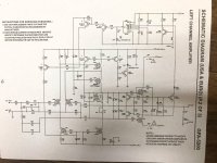
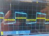
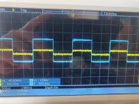
I've attached the schematics (I only have the schematics for the GFA-5200b; my unit is an older, simpler version) and the curves I measured with my oscilloscope at 40Hz and at 500Hz (blue is output).
Can anyone help me find and fix the problem?
I've attached the schematics (I only have the schematics for the GFA-5200b; my unit is an older, simpler version) and the curves I measured with my oscilloscope at 40Hz and at 500Hz (blue is output).
Attachments
Super quick simulation of a different amp but with similar time constants to yours. 40Hz signal. 2uF and series 22k (unseen at input source) and a1k8 and 47uF feedback return +47k feedback.

Dear Mooly,
thank you for your fast reply and for your explanations. I'm going to try connecting the amplifier to the speakers. I'm curious to see how it sounds.
thank you for your fast reply and for your explanations. I'm going to try connecting the amplifier to the speakers. I'm curious to see how it sounds.