I am adapting an existing balanced preamp chassis and power supply and need help. It is a 60v regulated supply with two 30v+30v transformers and two zener diode regulating chains. I want about 24v output. The schematic is below. The Zener are 9.1v each. First, can I use one of my existing transformers for both sections? Second, do I simply leave 3 active Zeners on each section, for 27v (+ and -)? Do I remove Zeners from the circuit by laying a wire across them or what.? Thanks
Attachments
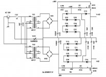
How much load current do you need? The pass transistor may get cooked due to the excess voltage.
It would be better to connect the two transformer secondaries in parallel for a lower voltage,
which would then be around 40V. Remove the existing connection between B and C.
Connect A to C, and B to D, to make the parallel connection instead.
Then the pass transistor would only drop 16V. You need 28V on the gate, so the Zeners should add up to that.
Use four series 6.8V 1W Zeners for the reference, operated at 60mA.
Short the other three positions for series Zeners, or remove them and replace each with a wire jumper.
Be sure to observe polarity for the new Zener diodes, make it the same as the ones that were previously installed.
The series resistor R101 should now be changed to 220 ohms, 2W.
Leave Z115 as is, since it protects the gate of the pass transistor. Also leave C103, C105, and R103 as is.
You still need to check on the power dissipation for Q101 under load.
All this applies only to the top circuit, as you don't need the bottom circuit if you only need +24VDC.
Last edited:
Thanks. Looks like load is no more than 100 mA. Also, I only need 18v - confused it with an amp project. So two of the 9.1v Zeners are just right it appears.
After considering the changes necessary, I think the better approach is to remove the existing PS and save it. I will look for a more appropriate PS and built that. Thank you, rayma, for jumping in to help. I’m still learning and didn’t appreciate what was required. And this way I will have a PS in reserve should the need arise.