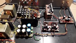
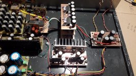
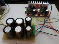
First, let me introduce my DAC, some have already seen it, but for those who haven't, it's a classic old-school DAC with DIR9001 as a digital receiver, PMD100 digital filter and 6 PCM1702s, three in parallel for each channel. The output current of 3 PCM1702s is 7.2mAp-p max. The power supply is given the greatest care, the PCB itself with DIR9001 has three ADP7118 regulators and they are the only IC reg. in the DAC. Other regulators, two +5V for PMD100, +/-5V for PCM1702 and the new +/-10V for AD811 are low noise shunt regulators, slightly improved, made according to Mr.Walt Jung's article and with the help of Mr. Walt. These regulators proved to be much better than the best IC reg ADM7150. There are three transformers to completely separate the power supplies of the digital and analog sections. The rectifiers use CRCRC filters to reduce the ripple as much as possible before the regulators themselves.
And now a little about AD811. AD811 is a high performance video and current feedback operational amplifier with 2500 V/μs. I used it for the first time about 15 years ago with a TDA1541 and two PCM1702, later I switched to tubes, but I wanted to give the AD811 a chance again because I think it deserves it.
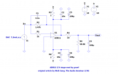
The scheme is from Walt Jung from 2/92, published in Audio Amateur, and that's how I connected the AD811 for the first time with op.amp nad filter after AD811. The difference is that now after AD811 there is nothing, the signal goes straight to the amplifier without any additional op amp and capacitor on the signal path. Between AD811 and Le Monstre amp is only the P&G 10K sliding pot.
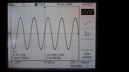
For this reason, a higher output signal of 3.34Vrms (9.52Vp-p) was chosen, and since the AD811 can provide 100mA at its output, there are no problems with driving the any amplifier at all.
The scheme of the I/V stage itself is simple, the only difference between the classic I/V is in the resistor R1 in front of the inverting input. The output voltage is simply calculated by the formula Vout=-Idac*R2.
The only audio filter(first pole) is R1/C1 and depending on the selected capacitor it ranges from ~40kHz for 2.7nF to ~49kHz for 2.2nF and it is calculated according to the formula fc=1/(2*pi*R1*C1) .
The size of the PCB is 42x80mm. All resistors are RN60 with 100uF/50V UKZ+ 10nF COG SMD for decoupling. The AD811 is an HF beast and should be treated as such. Small capacitors(C1,C5) can be polystyrene, mica or polypropylene.
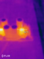
The supply voltage of +/-10V was deliberately chosen that way because of the heating of the AD811 itself, if a small heatsink is placed on them, supply voltage can be higher.
The story continues")
And now a little about AD811. AD811 is a high performance video and current feedback operational amplifier with 2500 V/μs. I used it for the first time about 15 years ago with a TDA1541 and two PCM1702, later I switched to tubes, but I wanted to give the AD811 a chance again because I think it deserves it.
The scheme is from Walt Jung from 2/92, published in Audio Amateur, and that's how I connected the AD811 for the first time with op.amp nad filter after AD811. The difference is that now after AD811 there is nothing, the signal goes straight to the amplifier without any additional op amp and capacitor on the signal path. Between AD811 and Le Monstre amp is only the P&G 10K sliding pot.
For this reason, a higher output signal of 3.34Vrms (9.52Vp-p) was chosen, and since the AD811 can provide 100mA at its output, there are no problems with driving the any amplifier at all.
The scheme of the I/V stage itself is simple, the only difference between the classic I/V is in the resistor R1 in front of the inverting input. The output voltage is simply calculated by the formula Vout=-Idac*R2.
The only audio filter(first pole) is R1/C1 and depending on the selected capacitor it ranges from ~40kHz for 2.7nF to ~49kHz for 2.2nF and it is calculated according to the formula fc=1/(2*pi*R1*C1) .
The size of the PCB is 42x80mm. All resistors are RN60 with 100uF/50V UKZ+ 10nF COG SMD for decoupling. The AD811 is an HF beast and should be treated as such. Small capacitors(C1,C5) can be polystyrene, mica or polypropylene.
The supply voltage of +/-10V was deliberately chosen that way because of the heating of the AD811 itself, if a small heatsink is placed on them, supply voltage can be higher.
The story continues
Attachments
AD811 can be used with any other current dac ; AD1862, TDA1541, PCM63, PCM1704, PCM1794 ... with correction of R1 and C1 values. The value of the output voltage can also be adjusted, the standard is 6Vp-p which corresponds to 2.1Vrms and should not go below that. Max output voltage also depends on the supply voltage, for example with +/-15V it is possible to get 24Vp-p without degrading the output signal. I doubt that anyone will need that much output voltage, but you never know. The input dynamic impedance should be below 1ohm.
The power supply is also quite important since the AD811 has a small PSRR of 70dB max. That's why I used the UnivReg_122714 shunt regulator from Walt Jung as a regulator. The regulator itself has been improved and uses a special low-noise reference instead of the LM329. The difference between this regulator and, for example, the LT3042 is that it is better in the audio frequency area, and with the use of quality op amps, it is possible to achieve really impressive results, high PSRR and low noise. The only drawback of this regulator is higher dissipation, which is typical for shunt regulators, as well as a rather large voltage drop on it (in this case 10V which is the minimum).
Soon I will raise the supply voltage to +/-14V because I intend to test some other op amps, for example AD797, OPA1641... as well as Burson Audio op amp. I hope to do all these tests on a DAC with quad TDA1541. I also intend to test some simple discrete I/V stages.
For +/-14V I will stick small BGA(or DIP) heat sinks on the AD811, without that I would destroy the AD811 very quickly.
Some will wonder what happened to the tubes that I advocated so much as the I/V stage, but more on that in the next posts..
Attachments
You had it done rigth using RN60 and not RN55 imho ! For C1&C5, although the value is only 0.1 nF , tin foil polystyren always gave me good results in my whole setup in that I/V critical area.
LCR has cool radial tin foil polystyren caps: 1%, 2%, 5% precision (Elements14, Farnell, Digikey ?) . Or just use the NOS Philips and Vishay tin foils that are excelllent. Think brandnew LCR are equivalents. But around the clock, I would use the new acrylic cap from Panasonic as a personal choice if you hear a difference in your whole setup. I do, but my mid and tweeter are metal cones, so very resolved (and full polycaps for the passive filter and Ayrton Perry resistors).
For the I/V resistor I would use the one that was benchmarked over a dozen in the post I made in Miro's ad1862 thread...
Last edited:
Hi, which series/types have tin foil?Or just use the NOS Philips and Vishay tin foils that are excelllent.
That are old NLA ones that have been used a lot in LP preamps, just let me a week to find it in my thoushand caps stock.... I should have also the old datashhet. But if you go with LCR it is imo as good. But as you didn't answer to my post about the pricing of Subbu V3 dispite I let you sold your in spite of mine (it is not for the fee but to troubleshoot a diya member... I am not sure it will be fast: notice I didn't send my V3 photograph to the asker... .
On a des manières ici !
.On a des manières ici !
Hi grunf - looks like a very interesting project, lots of attention to important details like power supplies. And AD811 is definitely my favourite integrated I/V.
I have a question - what's the reason for using the circuit with R1 (1k) in series with the AD811's -ve input? Is it because you want stability from a CFB amp with a cap (C1) in the feedback loop? ISTM just from ogling the schematic (no sims run yet) that including R1 is going to incur a significant noise penalty due to the 20pA/rtHz input current noise of AD811.
I have a question - what's the reason for using the circuit with R1 (1k) in series with the AD811's -ve input? Is it because you want stability from a CFB amp with a cap (C1) in the feedback loop? ISTM just from ogling the schematic (no sims run yet) that including R1 is going to incur a significant noise penalty due to the 20pA/rtHz input current noise of AD811.
I only use RN60 for audio and if power resistors are needed then the Ohmite WN series and that's it, I don't want to look for the perfect resistor anymore when there are much more important things that affect the sound than that.You had it done rigth using RN60 and not RN55 imho ! For C1&C5, although the value is only 0.1 nF , tin foil polystyren always gave me good results in my whole setup in that I/V critical area.
LCR has cool radial tin foil polystyren caps: 1%, 2%, 5% precision (Elements14, Farnell, Digikey ?) . Or just use the NOS Philips and Vishay tin foils that are excelllent. Think brandnew LCR are equivalents. But around the clock, I would use the new acrylic cap from Panasonic as a personal choice if you hear a difference in your whole setup. I do, but my mid and tweeter are metal cones, so very resolved (and full polycaps for the passive filter and Ayrton Perry resistors).
For the I/V resistor I would use the one that was benchmarked over a dozen in the post I made in Miro's ad1862 thread...
LCR polystyrene of 2.2nF(C1) was used in the first pole filter, I have a lot of them in the drawers. C5 is not that important and I could have put polystyrene there too but it is not necessary.
I paid much more attention to the power supply itself and suppression of HF noise from the digital part, these are much more important things to do in diy DAC.
In ds, I don't see any deterioration of the characteristics with an increase of the supply voltage, on the contrary, all parameters improve with +/-15V compared to +/-5V. The AD811 will be noisy if the source has high impedance, in this case it is low impedance.Isn't ad811 better suited for +-5V supply than +-10V ? I find it hot there and its noise isn't fantastic anyway.
Thanks @abraxalito, this is one project that has no end, first I got the maximum out of the tubes, now I'm going into battle with op amp and discrete IV stages.Hi grunf - looks like a very interesting project, lots of attention to important details like power supplies. And AD811 is definitely my favourite integrated I/V.
I have a question - what's the reason for using the circuit with R1 (1k) in series with the AD811's -ve input? Is it because you want stability from a CFB amp with a cap (C1) in the feedback loop? ISTM just from ogling the schematic (no sims run yet) that including R1 is going to incur a significant noise penalty due to the 20pA/rtHz input current noise of AD811.
But the first and most important thing is a high-quality and low-noise power supply and regulators. I'll talk a little more about that soon, especially as these regulators used in my DAC are the work of Walt Jung.
As for R1 itself, its purpose is CFA stability, in sym 470R is the minimum and I put the same value (1K) as Walt Jung in his IV stage with AD811.
I also don't notice any increase in noise from those 1K on -ve input.
Nope, not tried that. When I looked at the DS I thought its probably a bit too noisy. Guglielmo did though on his PCM1702 (or was it -4?) I think, and he also added a 5th order filter.
sure it uses no feedback, but I do find them clean enough... and better than many famous op.
@grunf : all is important, not only the powersupply. One can do it all... it is not about chasing the best parts but voicing the device according what you have, loudspeakers and so on.
Now, some loudspeakers are more forgiving, mine is aluminium mid and tweeters, all is heard for the better or the worse...
Last edited:
As for R1 itself, its purpose is CFA stability, in sym 470R is the minimum and I put the same value (1K) as Walt Jung in his IV stage with AD811.
I also don't notice any increase in noise from those 1K on -ve input.
You might find some inspiration from this paper which deals with getting stability with a feedback cap : https://www.ti.com/lit/an/slyt099/slyt099.pdf?ts=1668482772089. He uses a ferrite bead in place of a resistor in series with the -ve input - ISTM this will give a much lower noise penalty but his application isn't I/V so there may be some hidden 'gotcha' preventing such an approach in your case.
@diyiggy - I would agree it would be better than almost any opamp. But I reckon that's not a high enough bar
Yes. As I am remeber well, I first tried AD811 with PS of +- 14V cca. BUT i was stunned how it was hotFor +/-14V I will stick small BGA(or DIP) heat sinks on the AD811, without that I would destroy the AD811 very quickly.
These heatsinks refered in PDF, Aavid #5801, for easy mount on DIP8 are simply was not enough.
Even with bigger alu heatsinks temperature was pretty high for my opp. So I end up decreasing the power supply voltages to about something less of +-12V and with the bigger IC heatsinks. The T was significantly smaller but without change in sound. Measurements was slightly better.
It is not aceptable t use this IC without heatsink in any case. And maybe it is good to adopt some HS model with bottom and to areas and attach some bigger HS on top? Because probaly more heat comming from the bottom area?
Anyway I can say that AD811 has much better sound of any other OP in classic IV configuration. And clearly better sound from OPA861, I remember I tried in the same design to compare...
The device is obsolete. Be careful from used parts because in some brand designs I think they run them with +-15V or -+12V WITHOUT any heatsink! So they probably exhausted a lot from overhrating?
.
TI had one PDF with internal diskrete configuration examples of CFA. Cant remeber now which one... Maybe it is not bad idea to form the diskrete version. It will be of course much larger BUT the T can manage more eff.
.
Cheers
.
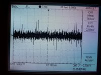
This is the noise measured with digital 0, i.e. when the filter and dac are working but without an audio signal, if I now compare it with the maximum output voltage of 9.52Vp-p, there is really no need to bother with noise. Much higher noise is obtained by passive I/V(resistor or transformer) conversion, especially when the tubes are behind the passive I/V.
Attachments
- Home
- Source & Line
- Digital Line Level
- AD811 as I/V stage for current DACs (and test some other op amps including Burson Audio op amps as I/V)