Opamps does not draw constant current when have output current.
Only when idle, the current flowing into supply pins are almost constant.
But ....
At positive voltage output, the opamp will need more current from V+ pin.
At negative voltage output more current is needed from V- pin.
Only when idle, the current flowing into supply pins are almost constant.
But ....
At positive voltage output, the opamp will need more current from V+ pin.
At negative voltage output more current is needed from V- pin.
While I'm greatful for the input, learning the importance of a low Z supply, I don't think this is what makes the sound. I've tried bypassing either just the transistor (using the 29R resistor) or the whole CCS, and I've tried to add more capacitance, and there's no audible difference. I think it's the topology and the choice of active components that make up most of the sound. I've tried simple emitter followers instead of the diamond buffers, but they sound worse.
The amp sounds very good, so extremely clean without sounding sterile. To me this still is the champ of opamps. In this amp I've only compared it to NE5534, AD825 and AD744, but I've compared AD797 to a lot of opamps in other amps.
I'm happy to say the discrete sounds almost identical to this amp, just slightly grainier, so I have to work harder on it, but I think it's a kind of a victory since I'm a novice, and it still beats the other monolithic opamps. There's room for improvement - better transistors in the current mirror and output stage, and better passive components. I'm also going to try a CFP input stage. It's a bi*ch to try to beat AD797 .
.
The amp sounds very good, so extremely clean without sounding sterile. To me this still is the champ of opamps. In this amp I've only compared it to NE5534, AD825 and AD744, but I've compared AD797 to a lot of opamps in other amps.
I'm happy to say the discrete sounds almost identical to this amp, just slightly grainier, so I have to work harder on it, but I think it's a kind of a victory since I'm a novice, and it still beats the other monolithic opamps. There's room for improvement - better transistors in the current mirror and output stage, and better passive components. I'm also going to try a CFP input stage. It's a bi*ch to try to beat AD797
.Sure the power supply "makes the sound"!
Why not replace the current source with a voltage source (properly backed up with caps of course)?
AD797 seems excellent. I think the AD847 sounds a lot like it. And OPA134 sounds like an AD product. I think perhaps OPA134 is better then OPA627, apart from perhaps some compression of dynamics.
Why not replace the current source with a voltage source (properly backed up with caps of course)?
AD797 seems excellent. I think the AD847 sounds a lot like it. And OPA134 sounds like an AD product. I think perhaps OPA134 is better then OPA627, apart from perhaps some compression of dynamics.
nelsonvandal said:While I'm greatful for the input, learning the importance of a low Z supply, I don't think this is what makes the sound. I've tried bypassing either just the transistor (using the 29R resistor) or the whole CCS, and I've tried to add more capacitance, and there's no audible difference. I think it's the topology and the choice of active components that make up most of the sound. I've tried simple emitter followers instead of the diamond buffers, but they sound worse.
Nelson, you have to learn one more thing, and that is your PSU, whatever it may be, IS in signal path...Now do you still think quality of PSU doesn't count?😉
Maybe we're sensitive to different colorations or maybe it has to do with the three channel architecture where the ground channel sinks/sources the return currents from the phones instead of capacitors and/or regulating circuits. I've learnt that the quality of the ground channel affects the sound as much as the l/r channels, and that should mean that the capacitors/power section in the more common two channel architecture are of equal importance.aparatusonitus said:
Nelson, you have to learn one more thing, and that is your PSU, whatever it may be, IS in signal path...Now do you still think quality of PSU doesn't count?😉
Like I said, I'm greatful for all your suggestions, and I learn new things every time I visit this site. I will try some kind of shunt regulator. It seems like a very good idea and I can see the theoretical benefits. Is the output impedance of such regulators lower than that of the capacitors going from rails to ground?
nelsonvandal said:
Maybe we're sensitive to different colorations or maybe it has to do with the three channel architecture where the ground channel sinks/sources the return currents from the phones instead of capacitors and/or regulating circuits. I've learnt that the quality of the ground channel affects the sound as much as the l/r channels, and that should mean that the capacitors/power section in the more common two channel architecture are of equal importance.]
I agree on all counts.
nelsonvandal said:Like I said, I'm greatful for all your suggestions, and I learn new things every time I visit this site. I will try some kind of shunt regulator. It seems like a very good idea and I can see the theoretical benefits. Is the output impedance of such regulators lower than that of the capacitors going from rails to ground?
Yes it does, except in HF range, but that is why you always see an capacitor at regulator output.
For super-shunt regulator start here: http://www.pat2pdf.org/patents/pat4366432.pdf
For super-shunt regulator start here: http://www.pat2pdf.org/patents/pat4366432.pdf [/B]
I guess I'd need two of those if I were to use it as ground, one from negative rail to ground and one from positive rail to ground, right?
He gets a patent for suggesting a shunt regulator after a constant current source!aparatusonitus said:For super-shunt regulator start here: http://www.pat2pdf.org/patents/pat4366432.pdf
Surely his application failed, even in 1982.
AndrewT said:He gets a patent for suggesting a shunt regulator after a constant current source!
Surely his application failed, even in 1982.
I'm not sure what you mean Andrew, are you applying that Noro should not get patent for super-shunt regulator?
I am also shocked to learn that such a widely used today topology was unknown in 1982.
Jonathan Carr suggests that STAX / Noro did indeed invent the super shunt reg: http://www.diyaudio.com/forums/showthread.php?postid=135373#post135373
MRupp said:Jonathan Carr suggests that STAX / Noro did indeed invent the super shunt reg
That's how I get interested in Noro's work, besides super-shunt regulator.
nelsonvandal said:
I guess I'd need two of those if I were to use it as ground, one from negative rail to ground and one from positive rail to ground, right?
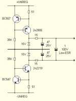
You need one for positive rail and one more for negative rail, just like in any type of regulated supply. Of course, you need to change polarity of transistors...You can even turn schematic blocks 40, 42, 44 up side down for more usual appearance.😉
Just one question regarding voltage regulators. Do I have to decide on an exact voltage the regulator will keep, or can they be made to follow a dropping voltage as the batteries are discharging?
I wouldn't recommend batteries as your voltage source with super-shunt regulator 'cos as the batteries voltage goes down so the voltage over resistor R1 in Noro's regulator goes down, meaning less current for shunt element (block 44). I would try trx -> diode bridge -> CRC -> super-shunt regulator.
It believe it can be made to follow a dropping voltage as the batteries are discharging, but I'm not that smart.😀
It believe it can be made to follow a dropping voltage as the batteries are discharging, but I'm not that smart.😀
I would be very surprised if the CCS + shunt had not been implemented by the Valve/tube guys long before transistors came on the scene. 1982 just seems wrong, particularly for a topology that, in hindsight, is so obvious.
I would be very surprised if the CCS + shunt had not been implemented by the Valve/tube guys ...
FWIW, I found the following comment from Steve Bench on shunt regulators: "The old tube based color TV's used a shunt regulator to maintain the picture tube "anode" voltage; typically using a 6BK4 as the shunt regulator element. Ditto for oscilloscope HV supplies"
I would assume that they used a resistor as current source for the shunt reg. to work against. Implementing a CCS with tubes seems to be too much effort and I am not sure if this was considered commercially viable in most cases.
P.S. Most anything looks obvious in hindsight 😀
Nelson,
do you really expect your sensitive ears to be delighted by the sound of this strongly mediocre topology?
Seemingly, you have infinite time and resources to waste and are not in the least troubled by going a long way around.
While your previous designs were moderately exiting, now you are steadily heading backwards. At least try to make one constructive step forwards and then two heavy steps backwards like when dancing skånsk mazurka...
- Status
- Not open for further replies.
- Home
- Amplifiers
- Solid State
- AD797, how to make the best of it