Hi folks,
I'm stuck with an old DSP PreAmp (cannot afford a newer one...) which works well, but does D>A with AD1853 followed by OpAmp I>V conversion and OpAmp driven Cinch outputs.
I'd like to implement balanced outputs and noticed applications which "just" use a 1:1 (or 2:1) Transformer with the DAC Chip Out+ and Out- and connect the transformer secondary to the balanced Cables/XLR.
My question (for lack of DAC knowledge):
Could I just cut the existing I>V (i.e. just not use both the existing I>V and the buffers driving unneeded cinch outputs) and instead connect the AD1853 Out +/- pins (12/13 & 16/17) directly to e.g. Lundahl LL7401 or LL2811 transformers' primaries and have the respective secondaries drive the balanced cables to the (already) balanced PowerAmp inputs?
Which other things should I consider? (Note: Volume control ist done in the digital domain, the existing PGA2310 is disabled anyway).
Thanks for your suggestions!
Regards,
Winfried
Last edited:
With a transformer output you need to implement the I/V conversion by a resistor either on the primary or on the secondary (or both).
But please note that the AD1853 needs an 1k load, and the balanced output transformers need a low impedance source drive, 10 ohms or so. The lower -3dB point can be calculated with the T=L/R formula, where T=1/ω, and ω=2 x π x f. Unfortunately L is not found in the data sheet, you need to measure it. L is the main inductance, measured with open secondary, in contrast to the leakage inductance which is mesured with shorted secondary.
But please note that the AD1853 needs an 1k load, and the balanced output transformers need a low impedance source drive, 10 ohms or so. The lower -3dB point can be calculated with the T=L/R formula, where T=1/ω, and ω=2 x π x f. Unfortunately L is not found in the data sheet, you need to measure it. L is the main inductance, measured with open secondary, in contrast to the leakage inductance which is mesured with shorted secondary.
Last edited:
@ lcsaszar
Thanks for answering! How do I specify the needed conversion resistor(s)? I do have the transformer datasheet (see links in the first post), but am not familiar with the "how to apply/specify" in practice...
Now as it seems, the AD1853 does not put out current but line voltage. At least this is stated on the Sowther website. So, is the recommended resistor needed then?
Regards,
Winfried
PS: Our Answers crossed... I'll check the Lundahl website for 1k transformers and the AD1853 for the output source resistance.
Last edited:
Hm, strange. The AD1853 data sheet on page 2 says:
Analog Outputs
Differential Output Range (±Full Scale w/1 mA into IREF) 3.0 mA p-p
On page 10:
Output Drive, Buffering and Loading
The AD1853 analog output stage is able to drive a 1 kΩ (in
series with 2 nF) load. The analog outputs are usually ac
coupled with a 10 µF capacitor.
The application example fig.29 is also a virtual ground circuit, providing very low load impedance.
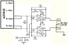
Well, looking at the App Fig. 29 it seems to me like that would provide reasonable decoupling of the DAC Outputs and may serve as balanced Output (if using appropriate Cable Drive capable OpAmps), maybe even replacing an output transformer:


What are your thoughts about these alternatives?
Regards,
Winfried
What are your thoughts about these alternatives?
Regards,
Winfried
Attachments
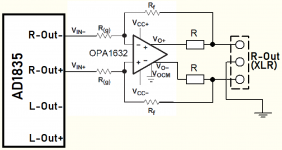
By way of some more research, another alternative came about: Usage of a dedicated Differential Line Driver. This seems quite simple, as this way the min. 1kOhm load for the DAC outputs can easily be implemented by matched R(g) and Gain with matched Rf, only one OPAmp per signal is employed and drive capability is inherent:

Looks almost too simple to be true (careful Vcc+ and Vcc- decoupling will obviously be added). Suggestions would be appreciated.
Looks almost too simple to be true (careful Vcc+ and Vcc- decoupling will obviously be added). Suggestions would be appreciated.
Attachments
I think the min 1k load should be max 1k. The application circuit in the data sheet omits them: the analog output goes to the -ve input of the op.amp directly (into the virtual GND).
Hi Jean-Paul,
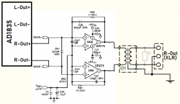
appreciate your comment! As I said, I'm not at all a DAC expert 😱 and was unsure about the necessary filtering. so, I have modiefied the schematic according to the AD1853 app notes:

Feedback is appreciated, so I can develop a final solution.
The feedback request is actually valid for the transformer approach as well, as it currently seems to me that a transformer solution may be technically equivalent, but at significantly higher cost!
Thanks and regards,
Winfried
appreciate your comment! As I said, I'm not at all a DAC expert 😱 and was unsure about the necessary filtering. so, I have modiefied the schematic according to the AD1853 app notes:
Feedback is appreciated, so I can develop a final solution.
The feedback request is actually valid for the transformer approach as well, as it currently seems to me that a transformer solution may be technically equivalent, but at significantly higher cost!
Thanks and regards,
Winfried
Attachments
Depends what you mean by technical, because it is guaranteed to measure a couple orders of magnitude worse; even with Lundahls
Thanks Inspector! You probably allude to e.g. the common mode performance of the balanded OP solution vs. the transformer being inferior there. Yes, I'm aware of that. Some say the transformer sound better, but if that would be worth the two- or threefold cost seems questionable to me. Actually, on the receiver side I do have a quite precise, professional OPA based balanced input stage at work.
Regards,
Winfried
Regards,
Winfried
The transformers do sound better when used after the opamps. So first active I/V and then transformers. I have used that setup in many DACs I built and even stock transformer boards with Haufe 1:1 transformers.
This is voltage output dac (PDF datas) with each output 2.8V P-P (1Vrms) and 180 ohm generator resistance.
So there is no need for I-V conversion in any way...
.
You can connect it directly with just one coupling Capacitir to the next stage. And depend on input reistor (potentiometer) of the next stage value of that C out is diferent. 10uF is for 10K in next. about 4.7uF for 22K, 2,2uF for 47K 1uF for 100K and more.
.
For my opp maybe just add some buffer at each output? It will be not highly demnding about the transformer too? because of the relatiely low internal reistance. BUT buffer will du beter job in that way. With very low output resistance buffer, almost all has, there will be much wider choice of interstage transofrmers? In terms of primary inductance (lower)...
Last edited:
Hello Zoran,
what you say seems logical and matches some of my thinking, but other Feedback suggested that filtering the output is necessary. What’s your feedback in this respect.
Thanks,
Winfried
what you say seems logical and matches some of my thinking, but other Feedback suggested that filtering the output is necessary. What’s your feedback in this respect.
Thanks,
Winfried
Anyway some fiter will be welcome? BUT maybe You will need some buffer to drive reactive passive 3 or 5 order filter?
I would cut out first very high Fo after the DAC Voutputs, then go to some High input impedance buffer (JFET or tube) then apply fiter.
Maybe after the buffe try interstage transofrmer? because XFRM will act as filter?
Not very sharp but still HF filter...
cheers and happy building 🙂
I would cut out first very high Fo after the DAC Voutputs, then go to some High input impedance buffer (JFET or tube) then apply fiter.
Maybe after the buffe try interstage transofrmer? because XFRM will act as filter?
Not very sharp but still HF filter...
cheers and happy building 🙂
This is voltage output dac (PDF datas) with each output 2.8V P-P (1Vrms) and 180 ohm generator resistance.
So there is no need for I-V conversion in any way...
I'm probably wasting my time but I'll give it a go anyway. The AD1853 has what AD call a continuous-time current-out analog DAC section. This means it needs an I/V stage. It is all in the datasheet should one care to read it. The AD1852 is voltage out.
Thanks rfbrw!I'm probably wasting my time but I'll give it a go anyway. The AD1853 has what AD call a continuous-time current-out analog DAC section. This means it needs an I/V stage. It is all in the datasheet should one care to read it. The AD1852 is voltage out.
As far as I'm concerned (being the thread starter) you're not wasting yout time!
I was a bit confused by the datasheet mentioning something like "line level output", not noticing that this may be meant to describe the AD1852. The DSP unit I'm thinking about modifying has a (probably I/V) stage with 1/2 OPA2134 per chip output which hints at what you say.
My intention with the project is actually to skip the analog DAC Chip output signal over as much of the analog postprocessing in the unit and feed that to balanced/symmetric output buffers. For example, I do not use the analog volume control and cinch output buffers.
Unfortunately, I do not have a schematic and the board is four layer, so reverse engineering is hard (for me). Hence, I now think about trying to at least identify the I/V and hopefully the filtering stage, cut there and connect that signal to the symm. output buffers. Originally I had hoped to do the I/V with a transformer, but that seems unexpectedly expensive and would need its own filtering...
Any feedback helps me!
Regards,
Winfried
OK folks,
I've had a closer look at the IV Application in the AD1853 DAC Chip Datasheet and also found an IV Bufferproduct called "Zapfilter" made for CD Player modification from LC Audio in Denmark (supposedly compatible with AD1853).
Here's an impression derived from the LC Audio website:

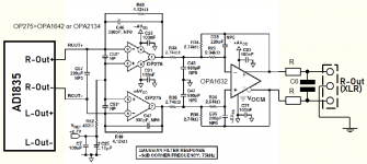
This lead to the following implementation idea based on the AD1853 AppNote, but using 2x OPA1632 instead:

The question left for me are the values of R1 and R3. According to the Zapfilter a low value would be appropriate, but actually, I have no idea on this important detail...
Hoping for help here,
Kind Regards,
Winfried
I've had a closer look at the IV Application in the AD1853 DAC Chip Datasheet and also found an IV Bufferproduct called "Zapfilter" made for CD Player modification from LC Audio in Denmark (supposedly compatible with AD1853).
Here's an impression derived from the LC Audio website:
This lead to the following implementation idea based on the AD1853 AppNote, but using 2x OPA1632 instead:
The question left for me are the values of R1 and R3. According to the Zapfilter a low value would be appropriate, but actually, I have no idea on this important detail...
Hoping for help here,
Kind Regards,
Winfried
Last edited:
- Home
- Source & Line
- Digital Source
- AD1853 I/V conversion transformer