Hello diyers,
This is my first post on this forum, and i want to present you my new DAC.
Ok, it's just another oversampling one, but i want to share this to help peoples who like me, encounter some problems during construction. I had some difficulties to make it working, but now it's quite ok. In advance, sorry for my bad english...
Presentation :
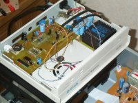
So, after tweaking for sometimes my cheap Sony CDP-XE330 i decided to build this DAC. This is my first one, so when i start the design, i want it too implements only the necessary functions, and to be a littely configurable after the board was done.
The receiver is an AD1892 asynchronous receiver. It's clocked by a PLL1707 at 24.576 Mhz (48kHz upsampling). A PIC microcontroler program the internals registers to choose the format of serial data.
The DAC is an AD1853 which is actually receiving 16bits words. I have planned to use 20bits words but during my first tests, I encountered a problem quite similar as this one :
http://www.diyaudio.com/forums/showthread.php?s=&threadid=19302&highlight=AD1853
but affecting the two channels.. It was less pronounced with 16bits packed mode. Now, i haven't precisely identify the problem (i have a very old scope with low bandwith, no memory), but it was solved by warming one more time all the pins of the CMS chip. 20bits will be tested soon i think 🙂
The I/V conversion, is a jocko homo simple implementation which sound really great (even if it's not the secret version 😉 ). Thanks for this jocko..
I have some questions about this point to finalize my board :
How to choose the current values ? Actually i have 10mA for the positive rail and 5mA for the negative. When i first test the board, i was using two identical CCS configured at 10mA each, and the sound was completely distorded. Can somebody explain me why ?
Also, i have not installed separated regulators for the two channels (I/V rails), and +15V and -15V are coming from simple power supply (LM317 regul). I was thinking of a simple zener+transistor solution to isolate the lines.. Will it add some noise ? What are the voltage reference more silent ? LED in series ? Some advices are welcome...
Thanks.
This is my first post on this forum, and i want to present you my new DAC.
Ok, it's just another oversampling one, but i want to share this to help peoples who like me, encounter some problems during construction. I had some difficulties to make it working, but now it's quite ok. In advance, sorry for my bad english...
Presentation :
So, after tweaking for sometimes my cheap Sony CDP-XE330 i decided to build this DAC. This is my first one, so when i start the design, i want it too implements only the necessary functions, and to be a littely configurable after the board was done.
The receiver is an AD1892 asynchronous receiver. It's clocked by a PLL1707 at 24.576 Mhz (48kHz upsampling). A PIC microcontroler program the internals registers to choose the format of serial data.
The DAC is an AD1853 which is actually receiving 16bits words. I have planned to use 20bits words but during my first tests, I encountered a problem quite similar as this one :
http://www.diyaudio.com/forums/showthread.php?s=&threadid=19302&highlight=AD1853
but affecting the two channels.. It was less pronounced with 16bits packed mode. Now, i haven't precisely identify the problem (i have a very old scope with low bandwith, no memory), but it was solved by warming one more time all the pins of the CMS chip. 20bits will be tested soon i think 🙂
The I/V conversion, is a jocko homo simple implementation which sound really great (even if it's not the secret version 😉 ). Thanks for this jocko..
I have some questions about this point to finalize my board :
How to choose the current values ? Actually i have 10mA for the positive rail and 5mA for the negative. When i first test the board, i was using two identical CCS configured at 10mA each, and the sound was completely distorded. Can somebody explain me why ?
Also, i have not installed separated regulators for the two channels (I/V rails), and +15V and -15V are coming from simple power supply (LM317 regul). I was thinking of a simple zener+transistor solution to isolate the lines.. Will it add some noise ? What are the voltage reference more silent ? LED in series ? Some advices are welcome...
Thanks.
Attachments

Hi,
I'm pleased to see some french guy at diyaudio !
I work for Atoll electronique as R&D engineer. Maybe I could help ?
Why the I/V converter uses only one output of the AD1853 ?
Isn't the problem ?
NETeagle
I'm pleased to see some french guy at diyaudio !
I work for Atoll electronique as R&D engineer. Maybe I could help ?
Why the I/V converter uses only one output of the AD1853 ?
Isn't the problem ?
NETeagle
That makes 3 french guys here 😉
Nice work, yanock! Can you explain the choice for this DAC IC?
Neteagle: can you please contact me by mail? I'd like to have some infos, about working in the HiFi industry 😉
Nice work, yanock! Can you explain the choice for this DAC IC?
Neteagle: can you please contact me by mail? I'd like to have some infos, about working in the HiFi industry 😉
What in earth is that massive "transformer" by the BNC connector for the SPDIF input?
It ain't gonna sound right with that thing in there........"I tell you what"..........
(That's Texan for all you guys in the EU.)
Jocko
It ain't gonna sound right with that thing in there........"I tell you what"..........
(That's Texan for all you guys in the EU.)
Jocko
Isn't that the spdif coupling transformer shown in the schematic? I was kind of wondering about it...
- Status
- Not open for further replies.
- Home
- Source & Line
- Digital Source
- AD1853 Dac with Jocko Homo I/V stage