well, i was using Polk's forums since i own and modded polks, and they recommended this place to learn about amplification.
i have read various threads about biasing the Acurus amps. specifically, i have an A250.
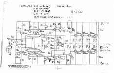
i have a schematic from hi-fi engine, and i understand it is to be measured across the emitter resistors, which are .5 0hm 2 w.
my problem is that i am newer than new, and i have little understanding of amp design. i have been trying to read and read, and when i look at the schematic, i see six 0.5 2w resistors.
i hate being new, but does someone have to plainly explain the procedure for this bias check? amp on? DMM setting? and exactly where to put the leads?
we have no repair shops in my iowa town and i would like to start learning some things on my own if i am going to be using vintage equipment.
thanks
steve
i have read various threads about biasing the Acurus amps. specifically, i have an A250.
i have a schematic from hi-fi engine, and i understand it is to be measured across the emitter resistors, which are .5 0hm 2 w.
my problem is that i am newer than new, and i have little understanding of amp design. i have been trying to read and read, and when i look at the schematic, i see six 0.5 2w resistors.
i hate being new, but does someone have to plainly explain the procedure for this bias check? amp on? DMM setting? and exactly where to put the leads?
we have no repair shops in my iowa town and i would like to start learning some things on my own if i am going to be using vintage equipment.
thanks
steve
Last edited:
ok...i'll try something more specific...
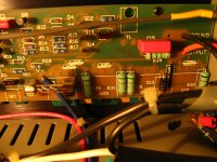
it was indicated that the emitter resistors are of the 0.5 ohm 2W variety. there are six of those. so will any one of them do, or is there a better one of the six to use?
the green ones correct?
it was indicated that the emitter resistors are of the 0.5 ohm 2W variety. there are six of those. so will any one of them do, or is there a better one of the six to use?
the green ones correct?
Attachments
Last edited:
well as long as i am talking to myself, i finally figured out which are the emitter resistors, and the bias of both channels was reading approximately 1.9 mv.... i have set it to 6 mv with +- 6.0-6.3 mv. letting it sit for a while with the DMM hooked up to monitor a little bit as there is a bit of more extreme fluctuation right after turning the pot.
maybe next i'll tackle my NAD 2150. at least i have a service manual for that.🙄
maybe next i'll tackle my NAD 2150. at least i have a service manual for that.🙄
so some of the harshness in the top end is gone.... but it also seems like i go longer on the volume to reach the same levels as before the bias adjustment. wonder if this is typical of bias adjustment, or possibly indicative of other problems?
the more i listen to it this afternoon... the deader it sounds. why would it have sounded livelier and more open when the bias was under spec?
Wow, no one seems to have heard you.
The correct bias setting for a class AB amp is 26mV (0.026V) across a single output transistor emitter resistor. So, looking at your schematic, if you measure across anyone of the emitter resistors and adjust the bias for 0.026mV you will have the correct bias current
However, some designs set a lower value to compensate for the internal emitter resistan of the output transistors (so called 're), but I would suggest you just set it as I described above.
Still other designs set the value higher in order to bias th output stage more into class A. In this design, assuming the Heatsinks are up to it, you could set the bias higher. Try .04V and see if the Heatsinks stay cool. This will give you a bit more class A.
Hope this sorts your problem out. Good luck.
Last edited:
thanks you very much... i remember you from the one thread i have been researching, and certainly appreciate your help.
so, the circuit will be able to handle that kind of current if the original bias spec was 6 mv?
so, the circuit will be able to handle that kind of current if the original bias spec was 6 mv?
I think the reason the bias voltage is set so low is because it will increase as the amp warms up. So set it for 6mV at room temperature and then leave the amp on for an hour or so and then measure the voltage again. You probably find it has crept up a bit to a more reasonable value. The 26mV figure by the way is called the 'Oliver' voltage after a guy from HP (Barney Oliver) who did a paper on this in the 1970's detailing why.
- Status
- Not open for further replies.
- Home
- Amplifiers
- Solid State
- acurus amp bias