Looking for some assistance, A250 no sound in right channel. I have 0.00 Volts at speaker output. I have +-85vdc on the rails, both fuses are okay. Nothing looks obviously wrong or burned. I think I could have a low side driver problem? I'm just not sure what to be looking for or at!
follow the schematic
use diode mode
check D1, D2, D3, D4, D5, D6, forward and reverse, see if any problem.
check from D2 to D5 for resistance,
a 200k resistor connect them in serial. if opened no sound.
check amp board ground wire connection, if opened no sound
check for bad joints, re-solder work might be needed.
there is less chance C7 220u/16v, if dry up no capacitance no sound.
Last edited:
I take it you have checked the one audio ground that goes via the RCA ground and chassis as indicated on the schematic?
Check the thermostat T1 and its connections, and the DC voltages on that string,
per post #2. That would be the most likely problem, being mechanical.
per post #2. That would be the most likely problem, being mechanical.
Last edited:
Shared album - Brandon Bisig - Google Photos
I have no schematics. The diodes are all correct. Unsure what was meant me connected to a resistor. Should I be measuring 200k across the diodes? Or to ground.
I have no schematics. The diodes are all correct. Unsure what was meant me connected to a resistor. Should I be measuring 200k across the diodes? Or to ground.
Acurus A250 Stereo Power Amplifier Manual | HiFi Engine
Check across T1 when cold, it should be a short. If not, it is bad.
Check across T1 when cold, it should be a short. If not, it is bad.
Looking at your picture, I highlighted two small transistors that appear to be cracked. Leads me to ask if you have you diode tested the transistors to see if any are shorted, measure faulty? That is where I would start.
Then I would take voltage measurements from the outputs directly (being careful with your probes).
Also when you say you get 0.0V on the output, is that direct from the board or at the speaker terminals? Asking since there may be a speaker protection between the board and speaker terminals and the relay might be open (triggered from DC voltage).
Attachments
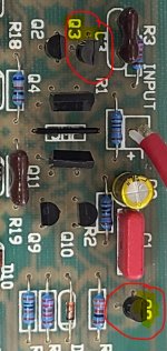
that's the manufacturing marks, not cracked. this amp does not have protection. I've only ever dealt with output transistor replacement. I'm not familiar on low side drivers!
update. have rail voltage on Q16 center pin. 0.0v on both outers. the working channel seems to be 4-10v AC when input was applied.
did you check the voltages of input circuitry as per post #4 and #2.
the strings of the diodes and the fuse T1, if opened will shut off the input circuitry power supply and the amp won't work thus to protect the amp.
if you had test the above,
you can compare the voltages of the two good and bad channels and write it down.
from the input to the output.. this could narrow down the fault
I failed to notice R4 being open. I replaced R4 and D1-D6. Now with no input connected I have lots of static and hum coming from that channel. I also noticed after putting a test speaker up in smoke in seconds I have between 10-41 -vdc on the speaker output. That makes me think bad output transistor. or could this issue still be on the low side. possible faulted capacitor?
your said you failed to notice R4 being open
so
for safety,
do you mind, let us know about your experience and your amp,
the length of time spent in diy,
around how many projects had been done and what kind,
do you fix amps often,
what kind of test equipments at hand,
has the schematic be thoroughly read and understood and know which is which,
do you aware this amp has fatal voltages in it
will you post detailed inside photos of the amp here
no offence, all for safety
Well aware of the voltages. 14 years ago fixed several car amps nothing in the home department. My first one. I've attached pictures of the the amp in question earlier in thread. I have never seen a DC output at a speaker connection yet. Additionally if I give the amp input I saw as high as 71v ac at the output. Only work I've done with this amp is board out of the amp and not hooked up. Just been far to long for me to remember how to test the transistors. This amp seems awfully simple but aside from tossing parts in it having trouble on a diagnostic.
thank you for quick responds,
you are right,
its simple, especially when we look at it as individual component first.
its only composed of resistors, transistors, capacitors, coils, fuses, diodes...solder joints...and they work as a whole...
if we check them individually,
for their value, conditions and find out the faulty one and replace it,
solder joints as well.
when every component is measured good then the amp should work.
the web is always a good helping hand.
to refresh
google how to use diode mode on multimeter
google how to use multimeter
it provides a lot of useful information to check the components.
Last edited:
Very familiar with use of a multimeter (auto technician) just not familiar with capacitor testing( does it need to be removed from the board?). And for the input transistos not sure how to find the issue or where to start. I could spend a boat load of time going back and forth between the good and bad channel but with the voltage on my output so high I would imagine it should stick out like a sore thumb
very good with a DVM,
get a transistor tester ESR frequency LCR Diode Capacitor meter squarer (all in one)
(around 18 USD) (the web will show the way to use it.) it is very helpful.
sometimes it is best to unsolder one leg or remove them from the board to check.
google how to use diode mode on multimeter
this will help to familiar with checking transistors, zener, diodes, shorts,..
to fix the DC offset on the output,
one must find out the faulty components first,
( unplug power cable to check )
normally check them individually, one by one,
check their values , conditions, this will help to find out the faulty one to replace.
solder joints as well.
they won't tell you they are faulty, unless one find it out with equipment.
don't need to switch on to check,
unplug,
use resistor mode or diode mode on the DVM,
to check the resistors values , transistors, diodes, ..
compare the two good and bad channels with the same components on the two amp board.
Looking at the schematic, am I blind where the board grounds to chassis ( via the speaker negative). Is it not drawn at go between c15 and audio ground?. With the output stage disconnected (removed r24-32) I'm getting DC voltage of ~+14vdc. When the power switch is turned off, it steadily goes to zero then climbs to about ~-17vdc. Trying to isolate the leakage. Nothing came up on a quick DVM test. Was going to try to split the board into sections to narrow down my work area!
- Home
- Amplifiers
- Solid State
- Acurus a250 no sound in right channel.