There are lots of good designs on both sides, its just that their performance aren't obvious to the naked eye...just to the ears.You better try them both , but start with the good ones, don't build some shitty one and judge the whole bunch because of that! It took me literally a whole year to see all the designs available on the internet a few years ago and read thousands of opinions about most of them...It never ends...Just build something that's worth the money first! I started with making some of the most craziest designs, but in the end you better think about the money you spend in this sport!
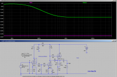
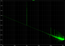
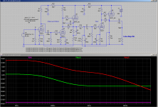
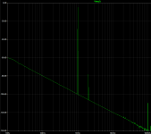
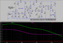
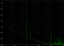
For example I did a quick back of the CRT scaling up of Broskie's first stage for tubes I have on hand and get the following. The simulated distortion results are many times better than the best I have seen in anything I have gotten using passive methods.
Attachments
Active has gain, passive only loss.
I've heard people say this, but it isn't true. The passive circuit uses all
of the available gain (in the bass). It's the active circuit that throws away
(open loop) gain and doesn't use it for amplification, in the feedback margin.
Last edited:
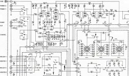
For some reason this schematic is sold by some, and for free you only find lower resolution pdf...Here's: Luxman a-3040
Is this the same as yours"
LUXMAN A3040 PREAMPLIFIER SCH Service Manual download, schematics, eeprom, repair info for electronics experts
Yes, it is , is just that i can't see the components clearly and their values.Is my PDF reader having a problem?
It's a jpeg, so it's not as good as it should be.
I know that some builders swear by a mix of PASSIVE and ACTIVE... Basically with RIAA you have 2 POLES and 1 ZERO ... The ZERO being the TURN-OVER frequency @ 500 Hz... If you properly place your 2 POLES, then ZERO will fall in place by itself ..... Some builder will put the 1 POLE active and the other POLE passive... I think some prefer to put the low frequency POLE in the active Feed-Back Loop and then have the High Frequency POLE as passive....some claim it sounds more natural in the highs and more controlled in the lows..
mine is a jpeg shot from the whole schematic, the relevant part for the phono schematic, but it's better than the pdf available on the internet for free.It's a jpeg, so it's not as good as it should be.
I know that some builders swear by a mix of PASSIVE and ACTIVE... Basically with RIAA you have 2 POLES and 1 ZERO ... The ZERO being the TURN-OVER frequency @ 500 Hz... If you properly place your 2 POLES, then ZERO will fall in place by itself ..... Some builder will put the 1 POLE active and the other POLE passive... I think some prefer to put the low frequency POLE in the active Feed-Back Loop and then have the High Frequency POLE as passive....some claim it sounds more natural in the highs and more controlled in the lows..
Or one could even use passive filtering and linear feedback gain stages to drive them. I am not sure that there would be any advantage over the full active filter but it could be another option. One possible advantage is that distortion would not vary as much with frequency.
The Broskie circuit would be easy to modify for the mixed approach you mention. Might be very interesting. Will definitely investigate that.
Last edited:
Or one could even use passive filtering and linear feedback gain stages to drive them.
That was done in the HK Citation I in 1959. Tubes, of course.
http://www.mcshanedesign.net/CitIschm.jpg
- Status
- This old topic is closed. If you want to reopen this topic, contact a moderator using the "Report Post" button.
- Home
- Amplifiers
- Tubes / Valves
- active v.s. passive phono