Hi,
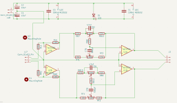
I have had PCBs made for an active tone control (schematic and PCB image attached). When I populated it (NE5532 opamps, fwiw) and tested it with my tone generator and oscilloscope it oscillates. The oscillation is in the form of a ~400mV AC on the 2V input sine waves. I forget the frequency of the oscillation but I can check if it helps and/or post pictures from the oscilloscope.
I think have narrowed down the culprit to the tone side of the circuit, not the input buffer, and I think especially the treble part (left side pot on the PCB). If I do any of the following - remove the tone-control opamp from its socket, turn down the treble pot completely or put my finger on the pins of the treble pot - the output signal is (fairly) clean. The circuit worked without oscillation on the breadboard so I assume it must be something about the PCB layout causing problems.
I've read about putting some capacitance in parallel with the feedback (resistor) to tame oscillating opamps but don't know if/how that would apply here as it'd be the whole tone network, not just a single resistor.
I would really appreciate any pointers on how to fix this, either in this layout and/or any suggested changes for a further revision.
Thanks!
Attachments
Does it oscillate if you apply shorting links to the inputs?
Are the supplies to pins 4 and 8 clean on the scope?
Are the DC conditions about correct i.e. around 0 volts on all pins apart from 4 and 8?
Adding a cap would be a small value like a 22pF from opamp output to the inverting input for each. Fwiw the component values (resistors) are an order of magnitude higher than be expected and this makes it all more prone to noise and instability... although in itself it should still work.

LM4562 has an offset voltage too. It's just lower than the NE5532's.5532 has an offset. Try LM4562
I see two fundamental issues in this circuit:
- No current limiting resistor on the LED (as pointed out above).
- Attempt to create an artificial ground point with two capacitors in series.
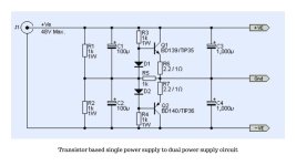
If you need the circuit to work with a single DC voltage you need to redesign it such that it creates an artificial ground rail somewhere around half the incoming DC voltage. An easy way to do this is to use a voltage divider with an opamp buffer. That can be a bit noisy, but it can work well enough. Alternatively, you can apply RC filtering on the VCC/2 "ground" reference for better noise performance at the expense of higher turn-on/off time and greater plop on startup.
The trouble with the rail splitter is that you really want chassis ground to be the negative terminal of the incoming voltage, which means that the AC ground floats above chassis ground, so you'll need AC coupling on input and output.
Creating a rail splitter with two 10 kΩ resistors across C2, C4 as suggested by Nico might just work. It it will have pretty high output impedance, so the ground potential will vary depending on the load imposed on this circuit, which may not be desirable, but it might work well enough.
A general note: The impedances in this circuit seem really high. That's not wrong per se, but you'd get better noise performance if you divided all resistors in the tone control part by a factor of 10 and multiplied the capacitors by a factor of 10.
Tom
I would suggest to use opamp in single supply configuration .. but too late for that.
So split supply seems the most practical solution.
So split supply seems the most practical solution.
Yup (assuming you mean just short either input to ground).Does it oscillate if you apply shorting links to the inputs?
Yup to that, too.Are the supplies to pins 4 and 8 clean on the scope?
And also that.Are the DC conditions about correct i.e. around 0 volts on all pins apart from 4 and 8?
That did it..! Thanks!Adding a cap would be a small value like a 22pF from opamp output to the inverting input for each.
Thanks for taking time out of your, no doubt extremely busy and important, day to denigrate me and offer no useful input. I do hope you feel better about yourself for it. I shall give up and never go near the topic again until I have a Master's in electrical engineering - or, far more likely, I won't.How could you design pcbs without having basic knowledge about fundamentals?! Full waste of time.
Great! so Mooly's advice helped with basic knowledge about fundamentals. 😎
Place 4x15k resistors on the NE5532 buffer stage instead of 4x100k.
Compensate the NE5532 buffer by adding a small capacitor (10pF, 22pF and similar) in parallel with RL5 and RR6. You should get a proper square signal at 1kHz when properly compensated.
Convert single supply to dual supply in one of the suggested ways (or convert the device to single supply).
Virtual GND (0V) should be connected to the chassis of the device.
Attachments

Last edited:

https://www.tubecad.com/2018/02/blog0412.htm
It is best to take a suitable transformer with two secondary windings and make a classic stabilized
dual power supply +-12 to +-15VDC.
It is best to take a suitable transformer with two secondary windings and make a classic stabilized
dual power supply +-12 to +-15VDC.
Last edited:
Apart from the errors in the thread above, opamps don't like capacitive loads. The simple way of avoiding this is to put 100 Ohm resistors in series with the output going off board
Thanks (almost) everyone for your help!
Regarding the floating ground I figured I would do a star grounded arrangement anyway so omitted the DC ground connection on the PCB (afaik connecting 2 grounds would be a loop and bad news (an aerial) anyway so why waste the PCB space). Is that misguided? For completeness I tried connecting the PSU's ground between C2 and C4 and it made no difference to the oscillation.
Also, the 'LED' on the PCB is really just a DC connection for an off-board LED with an inline series resistor (value tbd empirically) - somewhat misleading if you're not in my head, granted!
I'll definitely try the order of magnitude shift. As a first approximation I had used the values as suggested by Rod Elliot.
Given it worked on the breadboard though, and seemingly the 22pF across the 2nd opamp addresses the oscillation, is there anything obvious on the PCB layout causing it? Would it be prudent to add a capacitor across the opamp out and -in (in future designs) just in case?
Last edited:
Oh yeah, I forgot to say I had noticed that one already and in my testing I had included 100R resistors off-board but they didn't stop the oscillation.Apart from the errors in the thread above, opamps don't like capacitive loads. The simple way of avoiding this is to put 100 Ohm resistors in series with the output going off board
And why is this best? Just another transformer introducing more junk on the rails.https://www.tubecad.com/2018/02/blog0412.htm
It is best to take a suitable transformer with two secondary windings and make a classic stabilized
dual power supply +-12 to +-15VDC.
You went to so much trouble for a clean floating ground, why tie it to a noisy chassis and earthing, it has nothing to do with electrical safety.
- Home
- Design & Build
- Electronic Design
- Active tone control PCB opamp instability