Nordic - yes i know - but input voltages of arround +/-50V are rare - i don't know any opamp that can accept this high voltage input that is 100V peak to peak...
i have made a decision - i will try this thing to see if it is working with interconnect cables - if it is working i will try to make it work for speaker cables too...OPA604 or OPA2604 seems to be nice choice for interconnect cables active shielding......
i have made a decision - i will try this thing to see if it is working with interconnect cables - if it is working i will try to make it work for speaker cables too...OPA604 or OPA2604 seems to be nice choice for interconnect cables active shielding......
The theory is perfectly good and the technique is used in instrumentation as mentioned above. If you can insure zero volts across a capacitor, it effectively disappears. No dielectric absorption either, because nothing to absorb. The trick is the shield signal will have to match the real signal perfectly, in amplitude and phase, and that won't be easy. Remember, if you have a phase error, you'll have a voltage error, nullifying the technique. That means the best shield amp will be identical to your main amp. For HV op-amps, try the various ones made by Apex. Don't know if you'll find enough BW. IMO, the whole thing is probably a waste of time, but it might be useful to prove it to yourself- or make a useful discovery! You could make your own speaker cables, but a lot of people have been down that road, and getting low capacitance and low inductance and low resistance and low skin effect, is tough. Mostly they make expensive products that don't accomplish much. Me, I use heavy zip cord.
Conrad Hoffman said:The theory is perfectly good and the technique is used in instrumentation as mentioned above. If you can insure zero volts across a capacitor, it effectively disappears. No dielectric absorption either, because nothing to absorb. The trick is the shield signal will have to match the real signal perfectly, in amplitude and phase, and that won't be easy. Remember, if you have a phase error, you'll have a voltage error, nullifying the technique. That means the best shield amp will be identical to your main amp. For HV op-amps, try the various ones made by Apex. Don't know if you'll find enough BW. IMO, the whole thing is probably a waste of time, but it might be useful to prove it to yourself- or make a useful discovery! You could make your own speaker cables, but a lot of people have been down that road, and getting low capacitance and low inductance and low resistance and low skin effect, is tough. Mostly they make expensive products that don't accomplish much. Me, I use heavy zip cord.
thank You
i got aware of the "same phase" problem few hours ago....hmm...well, i begin to feel that this might not work after all...APEX is expensive company to my knowledge 🙁
anyway - i have some OPA2604 in my junk box and i have some RG coax. cable - i will try it to see... i think all of You and the guys on diyhifi.org forum might be right about this thing but i still want and will try it .... i don't know - i have a feeling it might be o.k. to try it so i will ... i might be crazy for doing that...
Well... a lot of inventors were considered crazy in the past.
go ahead....the worst possible result is to conclude things... and maybe some differences related your previous imagination.
And this is positive...one step you will climb to be more distant from the ignorance.
Related the Prisional Institution you already know what i think about.
regards,
Carlos
go ahead....the worst possible result is to conclude things... and maybe some differences related your previous imagination.
And this is positive...one step you will climb to be more distant from the ignorance.
Related the Prisional Institution you already know what i think about.
regards,
Carlos
cliffforrest said:How will you know if it "works" or not?
i will listen for myself and than go to one friend and make a blind test and to another friend to make another blind test.... if they confirm what i hear than i am on a right or wrong way.....
Carlos - thank You for the encourangement...
Great!..this is science...not subjectivism
The precision you will obtain from your results will be respectable.
regards.
Carlos
The precision you will obtain from your results will be respectable.
regards.
Carlos
well, i don't know if this will work at all.... or if i will make what i want to make...would this affect the sound - from my way of thinking probably not but there is this "what if.." that is bothering me ......
anyway thanks for the support .... i will see in few days when i get rid of the Eastern days of eating and drinking what i can do...
i will build the cable that is coaxial in design and same looking as my speaker cables...and also i will make that buffer using OPA2604 and will give a listen to it - with and without active shielding...
with shield to ground and also with active shielding powered on.....than i will know for sure.....
cliffforrest said:But what are you listening FOR?
Just a difference?
well, now we started a discuission that i don't want to write...
what we all are listening when we have a new cable in our system - a difference or something else - it is a discussion that is turning us away from the original thematic of this thread.....
of course i don't want to hear a difference 🙂
i want a cable that will sound better in my system related the original that i have....this doesn't mean that this will be better for any system....i want to build it for my system and to see if the sound is better or not - i don't want to have a difference - a diff. can be to the better or not ....
i want to have to the better sound....
🙂
Personally, I can't see it making a difference, but "What if?" is a fine and noble sentiment, so go for it! 🙂
thank You, thank You...
i begun to think i am crazy with this thing and almost said that i will leave it behind ....
i will quote here a post that a very kind guy called Nemestra has written on diyhifi.org forum only because of the papers he quoted there that are talking abotu this thematic - i hope he will not mind me doing that ..... also i hope that people here will not have anything against that.......
thanks Nemestra again...
=======================
Hi Sunrise and all,
I'm concerned that a simple and straightforward question from Sunrise should be met with unhelpful comments. It may be a bad idea for many reasons. Sunrise has indicated that he's aware of that. He would still like to try it out.
Sunrise, I haven't tried this with audio designs but am familiar with driven or guarded shield designs from front ends for physiological measurement, specifically electrocardiograms. The following are references on the subject which may or may not be helpful. They are all low bandwidth designs - ECG sampling / bandwidth rarely gets above 1kHz or so even for diagnostic quality 12 lead signals. As the bandwidth of the driven shield is increased system stability will be harder to maintain.
'High-quality recording of bioelectric events - Part 1 Interference reduction, theory and practice', A.C. Metting van Rijn, A. Peper, C.A. Grimbergen, Medical and Biological Engineering and Computing, September 1990
Chapter 6, Grounding and Shielding Techniques, 4th Edition, Ralph Morrison, John Wiley & Sons, 1998, ISBN 0-471-24518-6
Biophysical Measurements, Peter Strong, Tektronix Inc., 1970
Good luck,
James
========================
the thread can be found on this link, post 23
http://www.diyhifi.org/forums/viewtopic.php?p=26643#26643
Sorry for off topic, but what's the problem with cable capacitance?
Spread inductance should be high enough in most cases to make spread capacitance not important, all in all at high enough frequencies characteristic impedance is in tens of ohms range.
What do I miss?
regards
Adam
Spread inductance should be high enough in most cases to make spread capacitance not important, all in all at high enough frequencies characteristic impedance is in tens of ohms range.
What do I miss?
regards
Adam
probably already mentioned
flg: " ... I have worked with equipment, from a different field, That had to drive analog signals 20-30' down a cable. We used a double shielded cable. The inner shield was driven by a low power amp driving the same signal as the signal line. The outer shield was a gnd'ed shield. ... The theory here is that the signal line is in effect "cascoded" by the inner shield. ... "
This is the principle behind both USB and FireWire cabling, grounded outer shield (-), active power (+) on an inner wire or other shielding. This methodology is also related to those inexpensive TV coaxial cable boosters / amplifiers, shield as (-), center conductor as (+) = Electrons flowing down the outer shield (usually negative or grounded = 'cause that's where the electrons are). Cable capacitance / impedence is reduced, significantly in some cases ...
(This is, in principle anyway, the reason computer bus speeds have increased beyond "inactive" possibilities, like the PCI and PCI-x bus, etc.)
yes, they said that they used double shielding where outer shield has been grounded and inner shield is running the sam signal as hot wire inside (in center of the cable)...this inner shield is driven via buffer and this buffer has to deal with the capacitance that is between inner and outer shield - here i have only one shield so things are not good looking....
Re: probably already mentioned
I don't think this is the same at all!
Connecting a power supply to the screen has NO effect on the signal or capacitance.
A power supply IS ground as far as the signal is concerned (or should be!)
As for "electrons flowing down the outer shield" you need to look at your signal transmission theory again, I think!
FastEddy said:flg: " ... I have worked with equipment, from a different field, That had to drive analog signals 20-30' down a cable. We used a double shielded cable. The inner shield was driven by a low power amp driving the same signal as the signal line. The outer shield was a gnd'ed shield. ... The theory here is that the signal line is in effect "cascoded" by the inner shield. ... "
This is the principle behind both USB and FireWire cabling, grounded outer shield (-), active power (+) on an inner wire or other shielding. This methodology is also related to those inexpensive TV coaxial cable boosters / amplifiers, shield as (-), center conductor as (+) = Electrons flowing down the outer shield (usually negative or grounded = 'cause that's where the electrons are). Cable capacitance / impedence is reduced, significantly in some cases ...
(This is, in principle anyway, the reason computer bus speeds have increased beyond "inactive" possibilities, like the PCI and PCI-x bus, etc.)
I don't think this is the same at all!
Connecting a power supply to the screen has NO effect on the signal or capacitance.
A power supply IS ground as far as the signal is concerned (or should be!)
As for "electrons flowing down the outer shield" you need to look at your signal transmission theory again, I think!
inner shield = buffered signal
outer shield = ground
only i don't have that outer shield and i will use it only with buffered signal on the one and only shield i have..
outer shield = ground
only i don't have that outer shield and i will use it only with buffered signal on the one and only shield i have..
Example: USB
1) + Power = +5 VDC
2) Data 0
3) Data 1
4) - Power Ground = 0 VDC
5) Shield grounded, clamshell, tied at one end or both by connection to pin 4.
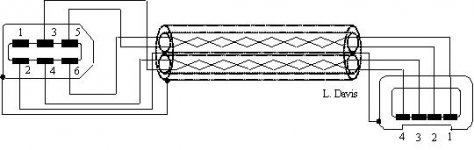
Example: 6 pin FireWire 1394a
1) + Power = + 12 VDC or greater = shield of one twisted pair
2) - Power Ground = 0 VDC = shield of one twisted pair
3) Data B receive
4) Data B transmit
5) Data A receive
6) Data A transmit
*) Outer shield = 0 VDC tied to 6-pin clamshell, one or both ends and tied to chassis ground
Note that current flows in both inner 1394a shields and can flow in the outer shield, thus aiding in impedence matching, etc. ... and also reducing EMF interference, internal and from the outside. The physics of all this is quite complicated, but it does work whether there is a dynamic flow of electrons or a static charge on the shield(s).
From: http://www.interfacebus.com/Design_Connector_Firewire.html
1) + Power = +5 VDC
2) Data 0
3) Data 1
4) - Power Ground = 0 VDC
5) Shield grounded, clamshell, tied at one end or both by connection to pin 4.
Example: 6 pin FireWire 1394a
1) + Power = + 12 VDC or greater = shield of one twisted pair
2) - Power Ground = 0 VDC = shield of one twisted pair
3) Data B receive
4) Data B transmit
5) Data A receive
6) Data A transmit
*) Outer shield = 0 VDC tied to 6-pin clamshell, one or both ends and tied to chassis ground
Note that current flows in both inner 1394a shields and can flow in the outer shield, thus aiding in impedence matching, etc. ... and also reducing EMF interference, internal and from the outside. The physics of all this is quite complicated, but it does work whether there is a dynamic flow of electrons or a static charge on the shield(s).
From: http://www.interfacebus.com/Design_Connector_Firewire.html
Attachments
"Note that current flows in both inner 1394a shields and can flow in the outer shield, thus aiding in impedence matching, etc. "
Can you please educate me as to what this means. I cannot see how DC current in the screen(s) has any effect on impedance.
Nothing in your link explains this, just a reference to differential signals inside a screen.
Thank you.
Can you please educate me as to what this means. I cannot see how DC current in the screen(s) has any effect on impedance.
Nothing in your link explains this, just a reference to differential signals inside a screen.
Thank you.
- Status
- Not open for further replies.
- Home
- Amplifiers
- Solid State
- active shielded speaker cables