Hello All,
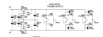
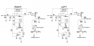
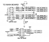
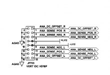
I'm trying to fix the active preamp stage of a creek destiny integrated amplifier. I've replaced both opa2134ua opamps and the surrounding electrolytic capacitors. I checked all leads, my soldering work, and for any shorts in the capacitors and resistors. I can't figure out why I'm hearing crackling and suppressed audio in both tracks. It sounds like music is underwater + cracking noises on the beats. But I can hear some of the music. The issue doesn't happen when I've turned off the active preamp (gain switch) The only thing I can think of is a "fit to oscillation" note in the schematics. I've attached the sections covering the active stage. The passive preamp sounds fine and I have no issues with the amp stage. If I'm reading the schematic correctly the tl072cd opamp is part of the passive stage, right? Any help would be greatly appreciated.
I'm trying to fix the active preamp stage of a creek destiny integrated amplifier. I've replaced both opa2134ua opamps and the surrounding electrolytic capacitors. I checked all leads, my soldering work, and for any shorts in the capacitors and resistors. I can't figure out why I'm hearing crackling and suppressed audio in both tracks. It sounds like music is underwater + cracking noises on the beats. But I can hear some of the music. The issue doesn't happen when I've turned off the active preamp (gain switch) The only thing I can think of is a "fit to oscillation" note in the schematics. I've attached the sections covering the active stage. The passive preamp sounds fine and I have no issues with the amp stage. If I'm reading the schematic correctly the tl072cd opamp is part of the passive stage, right? Any help would be greatly appreciated.
Attachments
That tiny cap shouldn't really be needed in that configuration and with those values, however...
Have you checked the supply voltages? Always do that first.
Check the output voltage of the opamps (on the 47 ohm resistors) is zero volts DC.
Could you be feeding to much signal into the front end and that is why using the gain switch causes the distortion?
No idea on the TL072 as it is not shown on the diagram (apart from the PSU)
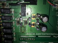
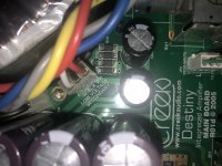
Thanks for your help! I've attached the rest of tl072cd, and a photo of the area. Creek audio sent me the complete schematics. I don't know if there's an issue with uploading the schematics in whole, hence the snippets. I managed to measure the voltage across the 47ohm resistors = 0Volts DC. The voltage across Vin and Vout on lm337imp and lm317emp is around 70mV DC. Is this expected? How do I measure the supply voltage? I tried to measure the 25+/- supply voltage by reading the voltage across lm317 (pin 3 according to the pinout on the datasheet) and analog ground = 0 volts DC. I used to have a grasp os analog and digital circuits about 15 years ago, much of the fundamentals have been forgotten. I know the active preamp was working as designed with the same inputs I'm currently using. Last year, I damaged something when I connected my dac to pre-out or power-in while the preamp and power amp were disconnected.
Attachments
Last edited:
You need to measure all voltages from ground which can be just the outer part of any of the RCA input sockets for convenience.
The voltage across the 47 probably would be zero under any conditions but what we really want is the voltage on the 47 ohm as measured from ground.
The supply voltage is easily measured by reading first to pin 8 on any of the opamps and then reading to pin 4.
You should read around PLUS 15 volts on pin 8 and MINUS 15 volts on pin 4.
The TL072 is just used as a buffer for the tape record output feed only.
Ok, first of all I double checked that my dmm is working on a battery - 1.3 volts.
The voltage on 47 ohm (from ground - outer part of RCA input) is 0 DC
The supply voltage measured from pin 8 to ground, and pin 4 to ground is also 0.
I'm pretty sure I'm reading the pins correctly. The small white dot on the opamp is pin 1, 2-8 are counted counterclockwise.
I checked the voltage from lm317emp pin 3 to ground, also 0.
So it looks like there's either an issue with the connection from the power supply on the main board to the preamp, or the analog power supply
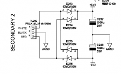
After turning off the power, I checked connections between the analog power supply (d213 and d214, and d215 and d216) to pins 7 and 9 on the main board, to pins 7 and 9 on the preamp board (no issues with the ribbon connecting the preamp to the amp). It looks like theres a connection issue between pins 7 and 9 on the preamp to lmp317 (pin 3) and lmp337 (pin 2), respectively. I sometimes hear a brief beep. Its strange because as far as I can tell the digital power supply works fine. Maybe I'm not reading the schematics correctly, or the schematics have some errors?
I checked voltages form d213 and d215 to ground - 30 Volts.
The voltage on 47 ohm (from ground - outer part of RCA input) is 0 DC
The supply voltage measured from pin 8 to ground, and pin 4 to ground is also 0.
I'm pretty sure I'm reading the pins correctly. The small white dot on the opamp is pin 1, 2-8 are counted counterclockwise.
I checked the voltage from lm317emp pin 3 to ground, also 0.
So it looks like there's either an issue with the connection from the power supply on the main board to the preamp, or the analog power supply
After turning off the power, I checked connections between the analog power supply (d213 and d214, and d215 and d216) to pins 7 and 9 on the main board, to pins 7 and 9 on the preamp board (no issues with the ribbon connecting the preamp to the amp). It looks like theres a connection issue between pins 7 and 9 on the preamp to lmp317 (pin 3) and lmp337 (pin 2), respectively. I sometimes hear a brief beep. Its strange because as far as I can tell the digital power supply works fine. Maybe I'm not reading the schematics correctly, or the schematics have some errors?
I checked voltages form d213 and d215 to ground - 30 Volts.
Attachments
Last edited:
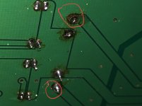
I fixed it! Last year I overheated the board while desoldering and the leads lifted on both of those 1000uF capacitors (C523 and C524) disconnecting the top and bottom pads. I was able to solder a wire from the top to bottom pad and resolder the capacitor. And that's the fix! Thanks for your help, I don't think I would have checked the power supply for quite a while - going in circles.... I really appreciate your help. I've attached photos for those who hopefully don't run into the same issue.
Best Gregory
Best Gregory
Attachments
Excellent news  well done.
(Checking all voltage supplies is pretty much the first rule in fault-finding, we never assume anything is correct until proved to be so🙂)
well done.(Checking all voltage supplies is pretty much the first rule in fault-finding, we never assume anything is correct until proved to be so🙂)
- Home
- Amplifiers
- Chip Amps
- Active Preamp Section: Replaced OPA2134UA - Crackle sounds