Hi, I'm a solder slinger so I was hoping someone more design savvy could check my schematic for a basic active splitter. This was designed to connect to the output of my R2R passive preamp, Vicol Audio's Maya. I don't need gain, just current, so this is meant to be a unity gain buffer. I have some old NE5532 that I plan to use, but I'm hoping the circuit is general so I can play with OPA1612 or OPA1642 if I'm unsatisfied. I also have some old Taka A5W-K two channel signal relays, which I would like to use to switch the outputs and bypass the buffer from the front panel. I'm planning to use a standard regulated PS with 7815/7915 (+-15V). Schematic is for one channel. One question is the location of the parallel film output caps. I put them on the output of the opamp rather than at the preamp output. My idea was that this would allow the buffer bypass relay/switch to retain as much as possible the current signal path of the passive preamp. All feedback welcome. THANKS!
.png")
Better to locate the first switch after the op amp, rather than shorting the op amp's + input and output.
In other words, you select either the input or the op amp output to go to the signal out.
To avoid pops you should add another 100k directly from the coupling cap output to ground.
Then the other 4 resistors are no longer needed.
In other words, you select either the input or the op amp output to go to the signal out.
To avoid pops you should add another 100k directly from the coupling cap output to ground.
Then the other 4 resistors are no longer needed.
Attachments

Last edited:

Revised below. Thanks rayma.
.png")
It is meant to bypass the active buffer. This is my only passive preamp and I want to be able to effectively switch the buffer on and off.Why the first relay??
I really just need the buffer, but I'd like the splitter to give me options for connecting active subwoofers or control a second system (amp and speakers) from the same sources and remote. I guess I'm just looking for flexibility to the extent it doesn't add a lot of complexity.How will you use the two outputs?
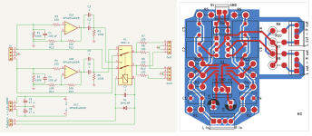
Hi All, I decided this would be a good project for me to learn how to PCB. It's simple and will allow me to build this buffer / active splitter to stack on my existing R2R with conveniently placed connections. I would really appreciate any feedback you have on the layout or revised schematic. I have removed the output selector relays since I don't have space for the switches on my front plate and I have added R11-14 to provide the ability to add gain, but can also be left open (R13,14) or replaced with a link (R11, R12) for a unity gain buffer. Thanks!

Attachments
Last edited:
I've edited the picture in post #7 so the edge cut is clearer in black and I've put the mounting holes in red. Thanks.Can you include the board outline also?
Like so? And then closer to the op amps pins 4 and 8 the better?You'll want to add some .01uF ceramics right next to the OPAMP power lines.
To increase the potential output current? I think a little explanation of "Why?" would help me learn a lot. Thanks!You have two outputs: it would be better to have a dedicated buffer for each one.
If one of the two outputs will sometimes be connected to switched-off equipment, you have to take into account that the line input of switched-off equipment may behave very non-linearly. When there is a common impedance in the paths driving switched-off equipment and driving the equipment you listen to, the non-linear behaviour of the input of the switched-off equipment may distort the signal to the equipment you listen to. In fact I had this issue with a switched-off Philips CDR 775 recorder, its record input is very non-linear when it is off.
Two very effective approaches to avoid this are to disconnect switched-off equipment or to give each output its own buffer.
A somewhat less effective method is to use a common buffer, but to split everything after it. That would mean splitting the two paths right at the feedback point of the op-amp, using separate AC coupling capacitors for the two outputs, separate relays or relay contacts and separate resistors.
Last edited:
Correct, and yes very close. When I place a board, I place these when I place the opamp to make sure they are right next to the opamp. The goal is 0 inductance between the cap and the supply pin. Some of these modern opamps have very large bandwidth.
- Home
- Source & Line
- Analog Line Level
- Active (opamp) output splitter