This is the PCB design. If the schematic looks correct and the PCB looks ok, then I'll not worry about the component values at the moment.
My immediate questions are whether I've drawn that peak filter correctly in the schematic, whether the overall design looks sound, and if the PCB looks ok.
V
My immediate questions are whether I've drawn that peak filter correctly in the schematic, whether the overall design looks sound, and if the PCB looks ok.
V
Attachments
Slightly off topic but can anyone recommend an inexpensive product for passive crossovers & notch filters? I played with the demo of LspCAD and liked it a lot. Unfortunately the cost for LspCAD (or SoundEasy) is killer when I only expect to use it 2 or 3 times a year. I tried playing with LTSpice but don't have enough of an electrical background to get it. I already use Martin King's MathCAD worksheets for enclosure design so I only need a small subset of LspCAD.
Help!
Help!
Holdent, you can use Speaker Workshop for passive crossovers. Plus it's free: http://www.speakerworkshop.com/
Matt, I've changed the first notch for a highpass. And thanks for all that info. It's got my face looking like this but I appreciate it 😉
Matt, David et al: Any further feedback on the last schematic/PCB would be appreciated as I'm going to order the parts soon as I can. Time's running out...
V
Matt, I've changed the first notch for a highpass. And thanks for all that info. It's got my face looking like this
but I appreciate it 😉Matt, David et al: Any further feedback on the last schematic/PCB would be appreciated as I'm going to order the parts soon as I can. Time's running out...
V
Hi Vikash
Don't know if it has been mentioned already. If you do many notches this way then the "resonant circuits" will mutually influence each other. The more the are spaced in frequency the less they do this. The effect of that is that you will have to fiddle around a little to get the right values.
Regards
Charles
Thanks, that would explain why the spreadsheet and spice models aren't always consistent. I guess a buffer after each stage would be the answer?
V
V
I guess a buffer after each stage would be the answer?
If it comes to ease of calculation - yes, definitely. But the price would be an increase of distortion and noise. So you'd have to pick your poison.
Good engineering is always picking the best compromise.
One possible compromise would be to generate two notches per stage that are spaced sufficiently.
Regards
Charles
Another rookie question: Does it seem like a good idea to replace the first resistor in each of the notch filters with a cheap trim pot?
Counter-question: Does it sound like a good idea to use a cheap trimmer to find the correct value by adjusting - and replace it with a fixed resistor afterwards ?
Regards
Charles
Regards
Charles
V,
I've had a quick look at your latest layout and everything looks fine. Now stop tweaking and start building!
I know you're intending to use the laser toner transfer method but it would be worth getting some etch resistant pens to touch-up any areas where the toner doesn't stick. The Staedtler permanent markers (for writing on OHP transparencies) resist the etchant for a while, but Dalo pens are the type to get. These contain an extremely thick lacquer-type ink which is specifically intended for PCB work. Both types are available from Mapo:
http://www.maplin.co.uk/Module.aspx?ModuleNo=2105&&source=14&doy=2m5
Nice one,
David.
With some notch topologies the first resistor also sets the center of the notch. IIRC, the topology Linkwitz uses the first resistor sets the frequency. The topology Jens Rasmussen used the first resistor sets just the depth of the notch. Simulate your notch changing the resistor to see if it affects the center frequency.
I think substituting a fixed resistor of the value discovered with the pot is a great idea.
I think substituting a fixed resistor of the value discovered with the pot is a great idea.
FWIW I use pots exclusively in my active crossovers, as I need them to be variable and they sound extremely good. Of course I have no comparison to using fixed values for all of them, but IME trimpots don't destroy the sound that badly, if they do anything, its benign.
I'm more concerned about unintentional tweaking. When the sub level on my XO was externally adjustable it always ended up as high as it would go after my daughter had been home alone. 🙄
My active speakers and therefore their XOs don't stay in any configuration long enough to worry about pots going noisy.
My active speakers and therefore their XOs don't stay in any configuration long enough to worry about pots going noisy.
Thanks David, I've finally got software working the way I want and I'm ready to get building 😉 I found a really good 'howto' using the laser toner method with little movie clips: http://esmonde-white.com/etching_pcb.html
I've looked into both methods (photoresist + laser) and like the idea of being able to just start again if the transfer doesn't work properly with the laser method.
Bob, Charles: Changing the first resistor changes the notch depth in this topology. I was thinking it might be useful to fine tune subtle driver to driver differences. The concern was whether the cheap ones will introduce any noise disadvantage over fixed resistors.
But then again, it's the caps (the ones that dictate the notch frequency and Q) that would really need fine tuning more than the depth.
Cheers Matt. I think I'll go with the trim pots if I can squeeze them into the PCB without altering too much...
Re: Re: Active Notch Filter design needed
I tried the Staples basic photo paper glossy and whilst the results are ok and useable with some touch up, it's not close to what you describe. The larger problem is the time it takes to peel the paper off - which is the better part of an hour (for a tiny PCB) even after it has been thoroughly soaked. The smaller problem is the amount of touching up required.
I wonder if the paper is actually different (it does have a different SKU to what you stated - but I figured it was just different in the UK): http://www.staples.co.uk/eng/Catalog/cat_sku.asp?CatIds=,&webid=S2t132&affixedcode=WW
The back of the paper has a very sticky residue when ironed - Is it possible the iron is too hot?
Nevertheless I'm chuffed to have made my first PCB. We'll find out tomorrow if it works or not!
Edit: Using a toothbrush, or rubbing the paper off with your fingers is futile. I had to scratch the paper off with my nails.
V
Hi Tom,gootee said:Sorry to barge in, like this. But maybe I have some helpful information...
Good luck.
- Tom Gootee
http://www.fullnet.com/~tomg/index.html-
I tried the Staples basic photo paper glossy and whilst the results are ok and useable with some touch up, it's not close to what you describe. The larger problem is the time it takes to peel the paper off - which is the better part of an hour (for a tiny PCB) even after it has been thoroughly soaked. The smaller problem is the amount of touching up required.
I wonder if the paper is actually different (it does have a different SKU to what you stated - but I figured it was just different in the UK): http://www.staples.co.uk/eng/Catalog/cat_sku.asp?CatIds=,&webid=S2t132&affixedcode=WW
The back of the paper has a very sticky residue when ironed - Is it possible the iron is too hot?
Nevertheless I'm chuffed to have made my first PCB. We'll find out tomorrow if it works or not!
Edit: Using a toothbrush, or rubbing the paper off with your fingers is futile. I had to scratch the paper off with my nails.
V
Attachments
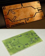
Wheey! Gratz on your first PCB^>^ it looks very good. I would say if you are gonna make many more PCBs in the future (once you've successfully made one your mind starts to think of other things you can make 😀 ) investing a little time and effort in learning/practicing how to get the artwork onto the board using transparencies and light etc, would be very worthwhile. It seems daunting at first, but once you've had a bit of experience at it, you can crank out the boards, ready for etching, very quickly, and there's relatively no mess!
Hi Matt, yep my mind's already racing. The possibilities, oh the possibilties!
I know it's only a simple circuit, but on flicking the switch and seeing everything work first time on your own design PCB is very gratifying indeed.
Now for the eq board. I've only got a week left to get the project finished
V
I know it's only a simple circuit, but on flicking the switch and seeing everything work first time on your own design PCB is very gratifying indeed.
Now for the eq board. I've only got a week left to get the project finished
V
Attachments
An externally hosted image should be here but it was not working when we last tested it.
An externally hosted image should be here but it was not working when we last tested it.
An externally hosted image should be here but it was not working when we last tested it.
An externally hosted image should be here but it was not working when we last tested it.
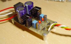
A special thanks to Matt and David

I'm happy with the preliminary measured response. Most importanly the circuit appears fine and now I just need to tweak some of the notch component values as they're not measuring exactly as modelled (no doubt due to interaction between them as mentioned earlier). But it's close enough to call this endevous a success. Now I've got a few days left to get it all built into an enclosure with amps...
V
Excellent work, the second PCB looks better then the first, I guess thats what happens with practice😉
I think the board looks rather 'cute', especially when you compare it with the monsters I've just built
Have you listened to it yet? I just finished mine a couple of hours ago its too early/late to listen to anything approaching a reasonable level.
What is the software you used there to measure the transfer function? I've been after something like that for a while.
Enclosures - Ah yes those pesky things, mine isn't big enough to fit these in properly 😀 One mono board is larger then the old stereo one🙄
I think the board looks rather 'cute', especially when you compare it with the monsters I've just built
Have you listened to it yet? I just finished mine a couple of hours ago its too early/late to listen to anything approaching a reasonable level.
What is the software you used there to measure the transfer function? I've been after something like that for a while.
An externally hosted image should be here but it was not working when we last tested it.
Enclosures - Ah yes those pesky things, mine isn't big enough to fit these in properly 😀 One mono board is larger then the old stereo one🙄
I've only listened to it brielfy in mono. The high pass has helped quite a bit it seems, and now the notches are 'hitting' where they should. The FR measures +/- 1.5 db to ~14kHz.
I used ARTA for taking the measurements: http://www.fesb.hr/~mateljan/arta/
V
I used ARTA for taking the measurements: http://www.fesb.hr/~mateljan/arta/
V
I'll round this thread off with pics of the final install and acoustic measurements:
Cheers all.
V
An externally hosted image should be here but it was not working when we last tested it.
An externally hosted image should be here but it was not working when we last tested it.
Cheers all.
V
- Status
- Not open for further replies.
- Home
- Loudspeakers
- Multi-Way
- Active Notch Filter design needed