Dear all,
I made a PCB design for an active subwoofer filter. It will be a 2 layer board. Because it has several potentiometers on the board edge, quite a few signal traces will end up in the ground layer.
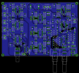
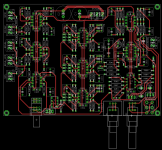
In this situation would it be preferable to still use a single ground pour like this:
Bottom:

Top:

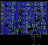
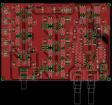
Or is it better to have ground pours in both layers like this:
Bottom:

Top:

Or doesn't it really matter in a situation like this (low frequency audio)?
Thank you for your input.
Cheers, Maarten
I made a PCB design for an active subwoofer filter. It will be a 2 layer board. Because it has several potentiometers on the board edge, quite a few signal traces will end up in the ground layer.
In this situation would it be preferable to still use a single ground pour like this:
Bottom:

Top:

Or is it better to have ground pours in both layers like this:
Bottom:

Top:

Or doesn't it really matter in a situation like this (low frequency audio)?
Thank you for your input.
Cheers, Maarten
I personally prefer to have such a big ground plane as can be done. I made several hand wrote PCB´s and using soft like autotrax for DOS, and use large ground planes, for two reasons: less copper and acid waste, and quicklier acid attack, and electrically is also better.
Bothn layers withground pours and stiching vias between the two pours, to join them together at multiple points.
Nice looking boards!
I do not use ground-planes in line-level based audio circuits. I prefer to keep the physical dimensions of the board to its minimum and pc traces as short as posasible with the maximum number of traces on the solder side. E
I do not use ground-planes in line-level based audio circuits. I prefer to keep the physical dimensions of the board to its minimum and pc traces as short as posasible with the maximum number of traces on the solder side. E
Ground planes for low level analogue do help keep noise down, I have seen them used on analogue designs for 27 years, and in't old days we wouldn't dreem of doing an analogue board without ground planes, pours.
The traces that are not power could be reduced in width a bit, they all look around 0.050".
The traces that are not power could be reduced in width a bit, they all look around 0.050".
marce: I agree that ground planes should be used on low-level signals. I use them there and also on high-gain narrow filter circuits. This one seems to be line-level with a gentle filter. Poorly implemented ground planes can all to easily end up as antennae. E
Yes, it is important to add stiching vias to at least both ends of a long thin strip of a copper pour, often overlooked or missed. I put my vias in a different colour to the copper and step through the design, visually checking there are vias in the right places.
Thank you all for your input. I'll go for the double ground pour then. Stitching vias shouldn't be a problem as the board will be manufactured by a PCB manufacturer and as such all ground connections will be plated through. I'll look into placing some extra via's on long thin stretches of copper to get a good connection between the two planes throughout the board.
- Status
- Not open for further replies.
- Home
- Design & Build
- Construction Tips
- Active filter ground pour