Filter-help
Calling filter-design-hotline:
I would like to make an active filter for the Altec Model 19...
I know the factory crossover is at 1200hz.
What else do I need to know, and how would you set up a filter for this?
Arne K
Calling filter-design-hotline:
I would like to make an active filter for the Altec Model 19...
I know the factory crossover is at 1200hz.
What else do I need to know, and how would you set up a filter for this?
Arne K
I have made many simliar filters with the "Active filter board" with very good results - mostly JBL systems with 2226 or 2235 bass with horn/compression drivers.
Most likely, you'll manage with two filter boards (and power supply, of course). Though I do not know the Altec drivers through personal experience, I would imagine the needed filter toplogy to be roughly similar: 4.-order filters, some eq on the treble horn and then you have one notch-filter "in reserve".
If you need more correction filters than this, you'll need 4 boards. I strongly recommend measuring equipment, though (the shareware ARTA is great) and some sort of filter CAD.

I suggest you start by modeling what the existing crossover is doing with the controls in the middle position and with idealistic resistor values substituted for the drivers.
Then add the driver inductance to Re for each driver and see what the model predicts for comparison.
That gives you a starting point.
If your preference for the adjustments is not middle, then measure your preferred settings and model them as well.
Then add the driver inductance to Re for each driver and see what the model predicts for comparison.
That gives you a starting point.
If your preference for the adjustments is not middle, then measure your preferred settings and model them as well.
Cobra2 said:So there are no way of "predicting" the setup without measuring?
(I got plenty of filter boards...)
With the HF horn, woud I need any baffle-step correction?
Delay?
Notch?
Arne K
Personally, I would definitely prefer measurements. The curves from the manufacturers tells little. In my experience, you'll always need some sort of frequency compensations, and for correct phase tracking between the units at crossover frequency, you'll (in practice) need to adjust the filters q-factor. Then, of course, is baffle step compensation (which, in turn, is dependent on speaker position, distance to back wall, etc).
Measurements is always the preferred methods - and the quality of the Model 19 drivers deserves it.
Re: Filter-help
Why?
It'd be a lot of work and then it wouldn't be an Altec anymore.
Cobra2 said:
I would like to make an active filter for the Altec Model 19...
Why?
It'd be a lot of work and then it wouldn't be an Altec anymore.
Re: Re: Filter-help
They does'nt last long inside a fireplace either...
It is reversable!
But if it is that difficult, I shuld have ordered a Behringer DCX.
I know nothing about sim-software.
Arne K
infinia said:
Why?
It'd be a lot of work and then it wouldn't be an Altec anymore.
They does'nt last long inside a fireplace either...
It is reversable!
But if it is that difficult, I shuld have ordered a Behringer DCX.
I know nothing about sim-software.
Arne K
Re: Re: Re: Filter-help
Oh I thought you were wanting to replicate the stock crossover in an active form.
Not too happy with the stock sound then.
Cobra2 said:
They does'nt last long inside a fireplace either...
It is reversable!
But if it is that difficult, I shuld have ordered a Behringer DCX.
I know nothing about sim-software.
Arne K
Oh I thought you were wanting to replicate the stock crossover in an active form.
Not too happy with the stock sound then.
Bob,
I am currently setting up a pair of AF boards with balanced input and Baffle Step Compensation (manual section 3.1.7). What is the intent for C9 in this scenario?
Thanks,
David
I am currently setting up a pair of AF boards with balanced input and Baffle Step Compensation (manual section 3.1.7). What is the intent for C9 in this scenario?
Thanks,
David
C9 is a bandwidth limiter in single ended operation. Omit it in the balanced connection. I should have mentioned that.
caution - I haven't looked at this in quite a while, and haven't finished my first cup of coffee today. 😉
caution - I haven't looked at this in quite a while, and haven't finished my first cup of coffee today. 😉
Continued from my last post...
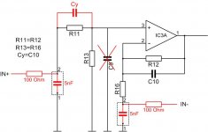
Ignoring for now the additional 5 nF caps and 100 Ohm resistors to add bandwidth limiting, I'm calculating unity gain for the positive input through out the audio range. Where as the negative input is showing the bafflestep gain. If I re-do the schematic as I've attached below the positive input gain tracks the negative input, just opposite phase. Did I miss something?
Thanks,
David
Attachments
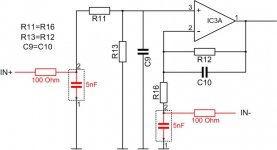
I cannot remember for sure, but I believe that you need another cap the same as you decided on for C10 to get balanced BSC. maybe it's break up R13 into two with the cap bypassing one part. A bit of a kluge, if the system has a spare buffer section, use that as a standalone BSC stage and set the balanced in as unity gain.
If you are just looking for ran input buffer, change C10 to something in the 100 pF range to eliminate any audio band step while rolling off RF gain.
Sorry I cannot be more help.
If you are just looking for ran input buffer, change C10 to something in the 100 pF range to eliminate any audio band step while rolling off RF gain.
Sorry I cannot be more help.
Help needed, I will trade skills
I abandoned my actve speaker project about 2 years ago but now I would like to finish it, but I need some help.
I'm looking for someone capable to help me out. I'd like you to design my crossover, source the components, build and test it. So not too much then !
I have the filter one pcbs and opamps. Reason I don't want to do it myself is that it would take a lot of time for me to design and source the parts, and then if it didn't work first time I would be pretty much stuck.
I could offer cash but that doesn't really seem in the diy spirit, I would prefer to offer my time. I'm handy with MDF, so I could make you some speaker cabinets, maybe some fancy shape. I could make you a monster 15" sonosub (got the parts!). Or how about a cool elliptical poker/dining table? Or maybe something in sheet metal.
IIRC, the filter one is similar to the AF4 minus the EQ and notches. Look back through the thread and find the spreadsheet. It works for the AF1 filters, too. Unfortunately that will give you fairly standard slopes. To add EQ and phase adjustment will take measurement in your enclosures and "some" value tweaking.
You can use Jens' idea and solder single pin sockets in for the resistors and filter caps to give you the option to change. Resistors are cheap - buy several values either side of the value that the spreadsheet gives you.
You can use Jens' idea and solder single pin sockets in for the resistors and filter caps to give you the option to change. Resistors are cheap - buy several values either side of the value that the spreadsheet gives you.
I've long been using a DSP (Sony srp-f300) for active filtering, delaying and EQ-ing my DIY speakers.

I've been using this setup for some years and now i'm looking to build something new and smaller: a pc speaker set, a portable audio set and a new HiFi set. Right now i'm working on the portable audio set. I don't want to abbandon the active filtering concept and i want to use this first project to learn from it. I'm not experienced when it comes to designing electronics or PCBs.
I've read about the active filter PCBs, are there still some availlable?
It's a system i built some years ago. Front speakers are three way active, with a Sony srp-f300 dsp as XO, delay and EQ. Amps are all Crest in a DIY 19" rack
The front speakers are hornloaded for mid- and high frequencies. Mid horn is DIY and made by plaster. Driver is a 6.5" Focal midbass driver. XO is set at 200Hz and 5KHz.
For HF a visaton HF hornloaded driver is used. And for lows, i started of with a 18" driver in a large BR, but that didnt work very well. So i replaced that with 2 15" TC Sounds woofers in an linkwitz style W-frame dipole (much better, but overkill).
The 5th 15" TC sounds woofer is used as LFE sub in an 150L closed box and powered by the 4th crest amp.
And all together 4 years ago:
But back to the PCBs: is there still a way to order the active filter PCB's? Or as an alternative, to get the PCB layout in pdf or eagle format so that i can order them at a local PCB-maker 🙂 ?
An externally hosted image should be here but it was not working when we last tested it.
The front speakers are hornloaded for mid- and high frequencies. Mid horn is DIY and made by plaster. Driver is a 6.5" Focal midbass driver. XO is set at 200Hz and 5KHz.
An externally hosted image should be here but it was not working when we last tested it.
For HF a visaton HF hornloaded driver is used. And for lows, i started of with a 18" driver in a large BR, but that didnt work very well. So i replaced that with 2 15" TC Sounds woofers in an linkwitz style W-frame dipole (much better, but overkill).
An externally hosted image should be here but it was not working when we last tested it.
The 5th 15" TC sounds woofer is used as LFE sub in an 150L closed box and powered by the 4th crest amp.
And all together 4 years ago:
An externally hosted image should be here but it was not working when we last tested it.
But back to the PCBs: is there still a way to order the active filter PCB's? Or as an alternative, to get the PCB layout in pdf or eagle format so that i can order them at a local PCB-maker 🙂 ?
- Status
- Not open for further replies.
- Home
- Group Buys
- Active filter board GB