Graham Maynard said:
I quite agree, and that is why similarly specified 0.01% THD specified amplifiers still *sound* different.
Not only 0.01%, the same is true for 0.003% for example.
Error Correction makes the case worse in back EMF issue?As will error correction amps, where loudspeaker voltage and current relationships become phase shifted.
lumanauw said:
Error Correction makes the case worse in back EMF issue?
I have not noticed anything like this.
Hi, PMA,
That tought comes after studying various EC schematic (including yours).
The EC always have feedback from output stage. In Hawksford, the signal comes to Collector/Emitor, and feedback from output is going to base.
In your EC, the signal comes to left emitors, and feedback comes to right emitors.
If we think that the output line (that connected to speakers) does only "obey" the EC, then it should be no problem.
But the back EMF is like rebelion. It makes its own distortion. In Hawksford, it goes straight to base. In your EC, it goes to right emitors.
So, if the signal at EC is "2 way" comunication, from input and also from output, (make the case your EC), the left emitors can control right emitors, but right emitors also can influence left emitors? Problem is, the signal at right emitors are full of back EMF, not clean signal (like when headed to resistive dummy load)
No,
I dont even have equipment to proove that back EMF exist.
As DIY'er without sufficient equipment, all I can do is like GM's way. He's writing like this :
If anyone does not believe me, then listen to an amplifier with headphones from another room as the output loading is switched between a resistor and a real world loudspeaker. Resistor operation will be as the THD specification suggests; but the THD specification will not be similarly relevant to loudspeaker loaded operation
PMA said:
Not only 0.01%, the same is true for 0.003% for example.
And less. I believe the spectrum will be audible at 0.001%
and possibly less, assuming a good enough replay system is
used.
Cheers,
Terry
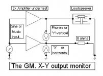
Hi PMA,
This is a test I use after I have a circuit up and running well with resistor loading; it is the sort of test that kicks you in the teeth.
The resistor/sine/THD might show good amplitude linearity, but this one shows back EMF induced (time) shifted conduction difficulties wrt the known good resistor response.
Cheers ....... Graham.
Attachments
lumanauw said:[snip]So, if the signal at EC is "2 way" comunication, from input and also from output, (make the case your EC), the left emitors can control right emitors, but right emitors also can influence left emitors? Problem is, the signal at right emitors are full of back EMF, not clean signal (like when headed to resistive dummy load)
Lumanauw,
I think you turn it around. Of course the EMF (if it exists) is at right emitters. It HAS to be, so that the EC can correct it. It is the same with feedback. You first have to have the error signal, otherwise you can not correct it. That also means that there will always be a small residual error left, however good the correction is.
In feedback, the residual comes from loop gain not being infinite.
In Hawksford EC, the residual comes from the correction gain not being exactly unity.
Jan Didden
Terry Demol said:
And less. I believe the spectrum will be audible at 0.001%
and possibly less, assuming a good enough replay system is
used.
Cheers,
Terry
The experience confirms what you are saying, most probably for the reason that it is not only single tone THD what we are speaking about.
lumanauw said:
Error Correction makes the case worse in back EMF issue?
I have played around with EC lately, and I can't detect a difference with a good feedback amp. The only difference I noted in engineering terms is that EC output stages are much more easy to get stable, often you don't even need any compensation.
But they show similar behaviour as feedback amps: very low output Z (high damping), freq response straight as a ruler, low THD. In fact, having two black boxes, one EC and the other nfb amp, you would be hard pressed to note the difference. Measurement wise the difference may show up as absence of ringing with square waves in the EC amp, and generally less hard clipping, but some feedback amps are also good in this respect.
Jan Didden
Hi, Jan,
Are you comparing one non-global feedback+EC with other amp that has global feedback?
How about the same global feedback amp, one without EC and one with EC, what is the difference in sonics?
Someone said that using parrareled many output devices can be as good as using EC. Is this true?
Are you comparing one non-global feedback+EC with other amp that has global feedback?
How about the same global feedback amp, one without EC and one with EC, what is the difference in sonics?
Someone said that using parrareled many output devices can be as good as using EC. Is this true?
Hi Lumanauw,
I was comparing a global feedback amp to an amp (my experimental setup) consisting of an EC output stage preceded by an open-loop VA-stage.
As far as multiple output devices are concerned, they lessen the impact of Hfe droop with output current, especially with low-Z (4 ohms or less) load. This was nicely documented by Douglas Self, although he presented it as a great discovery, which it wasn't of course. People have been using multiple devices for a long time, but Self put it on an engineering footing.
This is a separate issue from using multiple devices because of soa requirements.
Jan Didden
- Status
- Not open for further replies.
- Home
- Amplifiers
- Solid State
- 'active feedback' for distortion cancellation