Does anybody know a current source capable of whitstanding 5V/ns slopes whithout too much miller effect?
Common-base circuits do not suffer from Miller-effect. Apart from that a little Miller effect doesn't matter at all. The current supplied by this auxiliary current source would only be needed during a static condition.
Tonio:
Nice idea indeed but it might also suffer from draining under certain conditions.
Regards
Charles
fredos said:Why not use standard bootstrap and the circuit of WorkHorse only when output are near voltage rail? More efficient and less dissipative! Or like I use in some serie of amplifier, a bootstrap circuit with a 555 charge pump just to witsthand clipping condition...More efficient! 4 watts of lose is too much in a class d amplifier. The trick is only to find a way to hold voltage of hight side at clipping...
Fredos
Hi Fredos. Did you had any troubles during clipping, if standard bootstrap technique used (i mean ir2*** etc with UVP)?
I guess, that some troubles are possible, but due to other reason, and maybe at startup rather. For instance, one of most successful and reliable class D designs (like UcD) use 100uf bootstrap cap only, however idle current (ON state) ~4 times more then 350uA, so for ir2110 it's equal to 22uF.
Are you sure it is 100uF? It sounds like a lot to me.
For IR2110 I have had very good results with 1uF.
For IR2110 I have had very good results with 1uF.
UcD180 -100uF, UcD400 -220uF, but UcD drivers aren't CMOS like the ir2110, and their static ON_state consumption >1mA.
Just remember that a 20Hz hardly clipped signal need a hold time of 25 ms....That's means that you need large capacitance to hold it at a minimum of 10-12V to avoid that mosfet go into linear mode... Add to this idle current of driver itself, miller effect draining, temperature coefficient of component and leakage of capacitance....Bigger is better, but on other hand, it need more charging current, and in same way, provide more discharging current, lower the life of this capacitor. I use a 470uF, aluminium military type, with a 555 charge pump when output (common of mosfet) reach rail supply. So far, that's the only way I have found to got good result. Auxiliary supply is a good way too, but increase EMI if a single supply close to mosfet is not used for each top side.
Fredos
Fredos
For those who want to use a large cap I already made the following suggestion once (don't want to search):
Use a small cap as usual as main bootstrap cap like 100 nF for instance. Then use an "emergency cap" of larger size of which current is drained during long on-periods of the high-side driver. In order to make this current available quickly when needed without soaking the lower-driver's supply (as soon as the lower-side FET is switched on again) you use a Schottky diode and a parallel resistor between the two caps.
Regards
Charles
My experience with bootstrap cap is that, with higher values (I originally used 10uF), there was an annoying "tick" when powering up and down. With 1uF, it has almost disappeared.
Clipping behaviour is correct, on the other hand, even for low freqs.
Charles, some more details about your last suggestion?.... Thanks!
Clipping behaviour is correct, on the other hand, even for low freqs.
Charles, some more details about your last suggestion?.... Thanks!
UcD use 33kOhm pullup, for precharging bootstrap cap, and zener to clamp it at the 12V. I don't know too, why need the dedicated source or other bruteforce solution if standard circuit ok.. BTW, ir2110 and similar drivers, just can't provide 2-3A, even pulsed, long time at about 80-100C, so they need P-BJT follower at least, that will often safer for the ir2110 if the mosfet blew up.
Charles, some more details about your last suggestion?.... Thanks!
Below you can see what I am talking of. The components in the box are the additional ones.
Regards
Charles
Attachments
Hi, Charles,
What happens if I use only single bootstrapp capacitor Elko type, 100uF/50V without any 100nF in parrarell? Is this not good for operation of 400-500khz?
What happens if I use only single bootstrapp capacitor Elko type, 100uF/50V without any 100nF in parrarell? Is this not good for operation of 400-500khz?
My older UcD180 (11/04/2005) uses a 220uF 16V cap.IVX said:UcD180 -100uF
That's my thinking too. The brute-force method (a constant high side supply) should and obviously does allow the chip to work properly at high levels of low frequency clipping and even DC, but a larger bootstrap cap should allow proper operation even at high levels of low frequency clipping. That makes it sound like there was some other problem that made the bootstrap cap discharge too quickly or did not allow it to fully charge.IVX said:I don't know too, why need the dedicated source or other bruteforce solution if standard circuit ok..
Hi, Toino,
That's a clever design. I've tried such a cap multiplier for high-side, but coming from SMPS transformer (f=30khz), at that time it doesn't work, I think because the switching frequency of the classD high side is much higher than the SMPS (400khz compared to SMPS' 30khz)
That's a clever design. I've tried such a cap multiplier for high-side, but coming from SMPS transformer (f=30khz), at that time it doesn't work, I think because the switching frequency of the classD high side is much higher than the SMPS (400khz compared to SMPS' 30khz)
TOINO said:Hmmm... What about a secondary on the output filter coil? a few turns would suffice to give 10 or 12V for supply the gate driver.
It is also possible to derivate a kind of overload protection from that voltage…
🙄
Hmmm... what about hi side clip? Your solution suitable for 0<duty cycle<1 only, but don't work at duty cycle=1 🙄.
Hmmm... what about hi side clip?
The watchdog would be better than that IMO.
What happens if I use only single bootstrapp capacitor Elko type, 100uF/50V without any 100nF in parrarell? Is this not good for operation of 400-500khz?
I would definitely use a cap with low ESR close to the driver.
Regards
Charles
other solution is forced limitation of PWM duty cyclephase_accurate said:
The watchdog would be better than that IMO.
(0.05..0.95), that's allow avoid clip and also there is no need in huge military cap (470u 😉 )
Forced limit on duty cycle , but there are still some drawbacks associated with it as it adds additional "Pulse Edges" which might interfere with the switching cycles ....This technique is used in Crest amp LT1200.....
BWRX said:
That makes it sound like there was some other problem that made the bootstrap cap discharge too quickly or did not allow it to fully charge.
It could be another problem[parasitics, leakege current], but again brute force solves it....It has some drawbacks too as its subjected to high dissipation, but thats not so much of the concern when output power level is in kilowatts rather than watts...
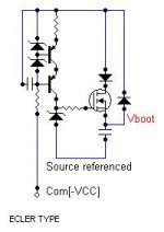
Eva said:Does anybody know a current source capable of whitstanding 5V/ns slopes whithout too much miller effect?

Yes I know one , its used in ECLER DT4800..It uses a cascoded current source for stable reference along with additional voltage source as well....The SW is 250kHz...The pass Transistor is ofcourse a Mosfet rather than bjt...
Attachments
- Status
- Not open for further replies.
- Home
- Amplifiers
- Class D
- Active Elevated Rail Hi side Bootstrapping Technique for IR2110