Based on famous principle of Tone Control by legendary audio engineer Peter Baxandall , After messing around in breadboard , I successfully designed a decent Tone control for Single Supply use for TPA3118 , TDA7297, TDA7376 . Now many people will Why go discrete when opamps are available . Well NE5532 on rail splitter did so up some noise on my CRO.
It uses very easily available components
I want to see how it performs on KSC1845 but for now i have used BC549B for buffer stage and BC549C for Tone Stage.
https://i.ibb.co/NjhPBRr/IMG-20200627-214541.jpg
Please have a look and any recommendation/criticism is always welcome to me.
Hope I spent my LockDown well on a fun little project
Pots are 100k each , Lower is treble whereas upper one is bass.
Edit: I fixed Typo and Schematic , Updated information about pots
Last edited:
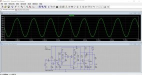
I want to see a LTSpice Simulation , anyone can help ? I tried but i cannot find all components and figure out how to set input and output signal
Sorry the schematic is wrong.
Well please can you point out i tried my best to copy from bread board
Last edited:
What is the value of the potentiometers?
Mike
I used two 100k pots from Alpha . I missed a 4.7k after pot with 0.033uf . Please wait i will fix my schematic.
Edit: Schematic fixed
Last edited:
4.7k resistor is missing, and 12V is to low voltage for that, it may be clipping at max positions of tone control.
Volume pot must be before this tone control.
Volume pot must be before this tone control.
Have a play with this if you want to practice simulating. R18 and R19 and R21 and R22 are the two 22k pots. So it is in the flat position here.
This circuit is very old and from Wireless World in the late 70's as I recall. It will give you something to compare to.
This circuit is very old and from Wireless World in the late 70's as I recall. It will give you something to compare to.
Attachments
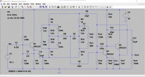
This one from Mooly looks better, with one transistor emitter follower as buffer, and two transistors for Baxandall.
But i still think that it will clip at 12V.
But i still think that it will clip at 12V.
Connection to the second transistor still wrong
I mistakenly drawn it to Collector . Sorry
This one from Mooly looks better, with one transistor emitter follower as buffer, and two transistors for Baxandall.
But i still think that it will clip at 12V.
Well i do not claim my design better than anything , I made what ever i could on a bread board , two 9V battery , spares lying around . I didnt clip on 18V supply though. Mad mans design not for serious use.😛
Thanks for help as_audio , nironiro and Mooly
When you put volume control before that circuit, you can control clipping with volume control use.
Sorry but your last editing 1h50 min ago is still wrong.
Baxandall network is getting "signal" straight from +12V rail and to boot is direct coupled, you need a coupling cap instead of the 38k resistor shown.
Baxandall network is getting "signal" straight from +12V rail and to boot is direct coupled, you need a coupling cap instead of the 38k resistor shown.
Sorry but your last editing 1h50 min ago is still wrong.
Baxandall network is getting "signal" straight from +12V rail and to boot is direct coupled, you need a coupling cap instead of the 38k resistor shown.
it will go to emitter , i have mistakenly made wrong schematic . SOrry
Last edited:
- Home
- Source & Line
- Analog Line Level
- Active discrete Baxandall Tone Control