I hadn't really intended to start a new thread at this time (I know it may seem odd, but this is only the fourth thread I've initiated), especially on this particular topic, but questions were asked about crossovers in another thread and there's a lot of misunderstanding, misinformation, and just general fog on the topic, so why not tilt at windmills for a few minutes...
First, a few caveats:
1) It'll take a while to put all the little bits and pieces together. That means a lot of writing time. And time, as you folks know, is in short supply. There's not really a lot of research to do, just the presentation of a whole lot of cookbook formulas and such. In other words, it may take a while to get all the relevant material put in here. My usual disclaimer: Be patient.
2) Nelson Pass has a crossover project coming in the near future (www.passdiy.com). All things considered, I imagine that most folks will go for his crossover, as it will be presented as a finished project (very likely with ready-to-go PC boards), whereas I intend to lay out the essential elements and leave it as mental exercise for you to calculate your own. I have no idea what topology he will use. It may or may not have anything in common with what I intend to put here. This is what I use; it's pretty minimalist. You can make it more elaborate, but you'll have a hard time reducing it. No, I won't feel at all insulted if you go with Nelson's project...for all I know, <i>I</i> may decide to go with it once he publishes it. Time will tell.
3) There are a lot of other crossovers out on the web. I've looked over a great number of them. Some look quite reasonable. Some are just plain...well, let's just say that they manipulate the signal, but not necessarily in the manner claimed by their designers. If you wish to use a crossover you find out there in the wilderness, keep yours wits about you. Test it thoroughly to make sure it behaves the way you want it to before putting it in your system. You have been warned.
Okay, down to business:
First off you'll need to determine your crossover frequency and the slope. Sorry, I can't do that for you. It'll depend on the speakers/drivers/cabinet configurations that you intend to use. There are literally millions of permutations. The one thing I'll say is that it's a good idea to leave at least one octave between the crossover point and any resonance or rolloff point so that the crossover slope has a chance to get established before the speaker/driver begins to assert its own character.
The next thing you need to determine is <i>how</i> you want to implement the slope. This gets into questions of Q (quality factor, i.e. how flat or 'humpy' the frequency response of the filter is), phase shift, and how fast the slope rolls off at the crossover point. This may sound confusing at first, but even though two filters may both be 12dB per octave, they won't necessarily roll off at the same rate. Twelve dB/oct will be the <i>eventual</i> slope, but will not be attained immediately. There will be a transition period where the slope is less, e.g. a Bessel crossover takes longer to achieve its slope than a Butterworth (but has less phase shift).
There are scads of crossover slopes and they all have perfectly valid uses. However, the three of most interest to us are Bessel, Butterworth, and Linkwitz-Riley. Note that the differences between these three tend to lead to emotional exchanges. I'll try to come back later and do a bit of contrast and compare between them, but I'd rather stay out of the emotional debates if you don't mind. Each has its positive aspects, each has its negative aspects.
Since most people have an idea as to how to calculate and implement a 6dB/oct (1st order--when someone speaks of the 'order' of the crossover, they're referring to multiples of 6db; a 2nd order crossover means 12dB/oct, 3rd order means 18dB/oct etc.), I thought I'd start with the 'other' building block, the 12dB/oct unit.
Note that these formulas are only for 12dB/oct crossovers. We'll cover 6, 18, and 24dB/oct slopes later.
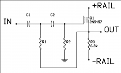
I've posted a schematic for the basic Sallen-Key high pass filter below. (Yes, I know the 2N5457 is a JFET but I'm using the symbol for a MOSFET--I haven't taught the program I'm using the symbol for a JFET yet.)
The formulas for the resistors and capacitors:
BUTTERWORTH
C1=C2 choose a value, to get started, try something in the 1000pF to 10000pF range
R1=0.7071/(2*PI*F*C)
R2=1.414/(2*PI*F*C)
BESSEL
C1=C2
R1=1.1017/(2*PI*F*C)
R2=1.4688/(2*PI*F*C)
Note that R3 doesn't really have anything to do with the crossover per se. It sets the bias current for the follower. I use +-15V rails, so this sets the current at about 2mA or so.
Device selection isn't that difficult. Essentially, you want a high input impedance and a low output impedance--which leads a lot of folks to want to use opamps. Go ahead, if that suits you. However, you don't need all that extra circuitry, as there's a ready-made circuit topology that meets the criteria--the follower. If you use a tube, JFET, or MOSFET, you'll have a very high Zin; somewhat less with bipolars, but still high enough that the crossover points will come out as predicted by the formulas. The Zout situation is reversed: bipolars are lowest, with tubes, JFETs, and MOSFETs coming in higher, but again low enough that the formulas will work just fine.
Incidentally, you'll need a DC blocking cap at the output.
Some people will want to know if you can substitute a current source for R3: Yes. Can you use P-channel or PNP devices: Yes. Can you use the DC blocking cap as part of the crossover: Yes. There's lots of latitude, here. Use your imagination. I'm just giving the bare bones. Don't be afraid to experiment. Your average small-signal transistor costs less than a dollar, frequently less than a dime. Fiddle with the circuit. Change things. Watch what happens with meters and oscilloscopes. Learn things. Enjoy yourself.
I'll be back later with the Sallen-Key low pass, then we'll tackle the other options as time permits.
Grey
First, a few caveats:
1) It'll take a while to put all the little bits and pieces together. That means a lot of writing time. And time, as you folks know, is in short supply. There's not really a lot of research to do, just the presentation of a whole lot of cookbook formulas and such. In other words, it may take a while to get all the relevant material put in here. My usual disclaimer: Be patient.
2) Nelson Pass has a crossover project coming in the near future (www.passdiy.com). All things considered, I imagine that most folks will go for his crossover, as it will be presented as a finished project (very likely with ready-to-go PC boards), whereas I intend to lay out the essential elements and leave it as mental exercise for you to calculate your own. I have no idea what topology he will use. It may or may not have anything in common with what I intend to put here. This is what I use; it's pretty minimalist. You can make it more elaborate, but you'll have a hard time reducing it. No, I won't feel at all insulted if you go with Nelson's project...for all I know, <i>I</i> may decide to go with it once he publishes it. Time will tell.
3) There are a lot of other crossovers out on the web. I've looked over a great number of them. Some look quite reasonable. Some are just plain...well, let's just say that they manipulate the signal, but not necessarily in the manner claimed by their designers. If you wish to use a crossover you find out there in the wilderness, keep yours wits about you. Test it thoroughly to make sure it behaves the way you want it to before putting it in your system. You have been warned.
Okay, down to business:
First off you'll need to determine your crossover frequency and the slope. Sorry, I can't do that for you. It'll depend on the speakers/drivers/cabinet configurations that you intend to use. There are literally millions of permutations. The one thing I'll say is that it's a good idea to leave at least one octave between the crossover point and any resonance or rolloff point so that the crossover slope has a chance to get established before the speaker/driver begins to assert its own character.
The next thing you need to determine is <i>how</i> you want to implement the slope. This gets into questions of Q (quality factor, i.e. how flat or 'humpy' the frequency response of the filter is), phase shift, and how fast the slope rolls off at the crossover point. This may sound confusing at first, but even though two filters may both be 12dB per octave, they won't necessarily roll off at the same rate. Twelve dB/oct will be the <i>eventual</i> slope, but will not be attained immediately. There will be a transition period where the slope is less, e.g. a Bessel crossover takes longer to achieve its slope than a Butterworth (but has less phase shift).
There are scads of crossover slopes and they all have perfectly valid uses. However, the three of most interest to us are Bessel, Butterworth, and Linkwitz-Riley. Note that the differences between these three tend to lead to emotional exchanges. I'll try to come back later and do a bit of contrast and compare between them, but I'd rather stay out of the emotional debates if you don't mind. Each has its positive aspects, each has its negative aspects.
Since most people have an idea as to how to calculate and implement a 6dB/oct (1st order--when someone speaks of the 'order' of the crossover, they're referring to multiples of 6db; a 2nd order crossover means 12dB/oct, 3rd order means 18dB/oct etc.), I thought I'd start with the 'other' building block, the 12dB/oct unit.
Note that these formulas are only for 12dB/oct crossovers. We'll cover 6, 18, and 24dB/oct slopes later.
I've posted a schematic for the basic Sallen-Key high pass filter below. (Yes, I know the 2N5457 is a JFET but I'm using the symbol for a MOSFET--I haven't taught the program I'm using the symbol for a JFET yet.)
The formulas for the resistors and capacitors:
BUTTERWORTH
C1=C2 choose a value, to get started, try something in the 1000pF to 10000pF range
R1=0.7071/(2*PI*F*C)
R2=1.414/(2*PI*F*C)
BESSEL
C1=C2
R1=1.1017/(2*PI*F*C)
R2=1.4688/(2*PI*F*C)
Note that R3 doesn't really have anything to do with the crossover per se. It sets the bias current for the follower. I use +-15V rails, so this sets the current at about 2mA or so.
Device selection isn't that difficult. Essentially, you want a high input impedance and a low output impedance--which leads a lot of folks to want to use opamps. Go ahead, if that suits you. However, you don't need all that extra circuitry, as there's a ready-made circuit topology that meets the criteria--the follower. If you use a tube, JFET, or MOSFET, you'll have a very high Zin; somewhat less with bipolars, but still high enough that the crossover points will come out as predicted by the formulas. The Zout situation is reversed: bipolars are lowest, with tubes, JFETs, and MOSFETs coming in higher, but again low enough that the formulas will work just fine.
Incidentally, you'll need a DC blocking cap at the output.
Some people will want to know if you can substitute a current source for R3: Yes. Can you use P-channel or PNP devices: Yes. Can you use the DC blocking cap as part of the crossover: Yes. There's lots of latitude, here. Use your imagination. I'm just giving the bare bones. Don't be afraid to experiment. Your average small-signal transistor costs less than a dollar, frequently less than a dime. Fiddle with the circuit. Change things. Watch what happens with meters and oscilloscopes. Learn things. Enjoy yourself.
I'll be back later with the Sallen-Key low pass, then we'll tackle the other options as time permits.
Grey
Attachments
Thanks for the info Grey!! 🙂
For those of you who still haven't read the article about bi-amping, here it is.
http://sound.westhost.com/bi-amp.htm
For those of you who still haven't read the article about bi-amping, here it is.
http://sound.westhost.com/bi-amp.htm
Grey,
Looks like you could replace R3 with a current source, possibly another 2N5457 with a trimpot between the source and gate to adjust for offset.
Cheers,
Jam
P.S. Another 24 posts and you will be a DIYaudio Grandfather.
Looks like you could replace R3 with a current source, possibly another 2N5457 with a trimpot between the source and gate to adjust for offset.
Cheers,
Jam
P.S. Another 24 posts and you will be a DIYaudio Grandfather.
Jam,
Us grandpa-types tend to get senile...I thought I put in somewhere above that R3 could be replaced with a current source. If I didn't, well, I meant to, maybe that counts for something. Keep in mind that the gate is tied to ground via R2, so if you use a pot, you can adjust the bias, but I don't think you'll manage to achieve 0V DC offset at the output.
Once upon a time (back before you could chose your own tag line), Jason asked me if I wanted something other than Elder under my name. I told him that I couldn't think of anything, so perhaps the best way to go at it would be to put it up for a vote. Then an attack of sanity came over me and I realized that some of the things that folks 'round here might want to call me might not be printable, at least not on a PG-rated site. So in the end I decided I'd just kinda hang with the default.
Besides, I ain't <i>that</i> old...just 43. I just act grumpy a lot and it convinces people that I'm this nasty old curmudgeon. Frequently, it's just because I'm running on four hours of sleep and can't think straight. Oh, well.
Now, if you'll pardon me, I think I'll dodder off on my cane...can't remember where I put my Geritol.
Grey
Grey, your not that senile 🙂 in your original post you did indeed mention that R3 could be replaced with a current source. btw what do you currently use for drawing schematics? i and getting tired of the 50 part limit on the version of CircuitMaker i use.
Grey,
Not being a spring chicken myself (46), I realize that I should have said that the current source could be modified to zero the offset.
The reason that this can be done is a j-fet is a depletion mode device. This is how you do it:
1) Remove R3 and attach a ,say, 47 ohm resistor to the source, the other end is the output.
2) At the output connect a drain of another 2N5457.
3) Connect the source and gate of the second fet with a 100 ohm trimpot.
4) Connect the gate of the second fet to the negative rail.
You can now adjust the offset with the trimpot. It helps if the fets are matched for IDSS, so you do not need an output coupling capacitor(good). This circuit works well in my experiments.
Cheers,
Jam
P.S. I wonder if Geritol mixes with Vodka. 😉
Jam,
Huh...forget the vodka, Geritol's got enough alcohol in it to strip the paint off a shrimp trawler. Tastes awful, though.
Now, the wine I had with dinner tonight--now, <i>that</i> was tasty.
Da, I see what you're saying about the 47 ohm resistor. That would work. But sneaky me, I make that DC coupling cap do double-duty, as I need the extra slope. Still, if all someone wanted was 12dB/oct, it should do the trick.
AudioFreak,
We recently had a thread wherein we thrashed around for a bit looking for a program that would output a decent schematic. Geoff was kind enough to be a guinea pig and test a few programs and came up with two suggestions. I chose to go with Circad because it doesn't have a pin limit and an amp schematic I recently drew up had well over 200 pins. The other candidate Geoff suggested had, I think, a 100 pin limit, but I believe that Geoff's opinion was that it was easier to use. Can't remember the name of the other program (senility again) so you'll need to check the thread to see what he was recommending. Circad seems to work well for schematics (see schematic above). I haven't yet done a board with it, although I've begun a preliminary layout. The library files have a few notable gaps (N-channel MOSFETs, but no P-channel), but it's not too hard to reverse engineer their format and create your own. I just haven't gotten around to doing something about the JFET symbol yet.
Grey
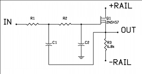
The Sallen-Key 12 dB/oct low pass filter will look familiar if you've seen the high pass. It's just that the resistors and capacitors played musical chairs while your back was turned.
For those who've noticed that one leg of the filter goes to the Source and wondered about it, bear in mind that the Source/Cathode/Emitter is another input to the device, a non-inverting one. This is why opamps aren't the be-all, end-all--you don't need ninety transistors just to provide an inverting input and a non-inverting input. One little-bitty device can do the job, all by its lonesome.
For extra credit: Think carefully. Where have you seen this before?
(Hint: a Certain Patent is based on using this trick for distortion cancellation during amplification...)
Formulas as follows:
BUTTERWORTH
R1=R2
C1=1.414/(2*PI*F*R)
C2=0.7071/(2*PI*F*R)
BESSEL
R1=R2
C1=0.9076/(2*PI*F*R)
C2=0.6809/(2*PI*F*R)
To build a band pass, you simply put a high pass filter and a low pass filter together, back-to-back, each set for one end of the frequency range you want.
In principle, and assuming that you attend to a few minor details, you now have enough information in hand to design a complete working crossover.
But that doesn't mean we're done yet...
Grey
Attachments
oh .... I know ... I know ... I know ... I know ... I know ...
Nelson Pass of Pass Labs
Super Symmetry (su-sy)
Nelson Pass of Pass Labs
Super Symmetry (su-sy)
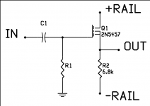
Time to put it in reverse and do the basic 6dB/oct. filter high pass section. There's only the one formula this time:
R1=1/(2*PI*F*C1)
although if it makes you happy, we can solve it for capacitance:
C1=1/(2*PI*F*R1)
At least that way, we make things look complicated by putting in more formulas.
The reason that there's only the one formula is that there's no Butterworth 6dB/oct. calculation. It's technically a Bessel, which is why people are always talking about how 6dB/oct. filters are better in the phase realm. It comes to them naturally.
By the way, you should memorize that formula, as there will be a quiz Friday. If I wake you from a sound sleep, you should be able to mumble that formula without hesitation. Why? Because it's just about as fundamental as Ohm's Law.
And AudioFreak gets this week's gold star, but if he doesn't stop passing notes to Susy, I may just take it away...
Grey
(By the way, Jam, if I've timed it right this should be post #1000.)
Attachments
Hello all,
Why don't you try a Linkwitz-Riley ?
They are squared butterworths (2 butterworths cascaded) and have constant group delay.
The cut-off is 24db/octave.
grtz
Simon
Why don't you try a Linkwitz-Riley ?
They are squared butterworths (2 butterworths cascaded) and have constant group delay.
The cut-off is 24db/octave.
grtz
Simon
Patience, Simon.
I believe I said above that it would take a bit to get all the entries in place...
Grey
I believe I said above that it would take a bit to get all the entries in place...
Grey
guys, might wanna look at www.rane.com for beautifull info. on active filters....check out the 'downloads' page
I have no problems viewing any of Grey's attachments in this thread so the problem must be related to your computer or your internet service provider.....
Sam
Grey's schematic does not appear in the thread (unlike those in some other posts). You need to click on the file name, save it to your hard disk and then view it from there.
I must admit I prefer this method of viewing images since it saves time when accessing a thread.
Geoff
Grey's schematic does not appear in the thread (unlike those in some other posts). You need to click on the file name, save it to your hard disk and then view it from there.
I must admit I prefer this method of viewing images since it saves time when accessing a thread.
Geoff
I'm not sure why some images show on the screen and some have to be downloaded. I am assuming that Jason has a limit on the size of the image that will show by default, or perhaps it's by file type. The GIF files that Geoff created from my Aleph PCB layouts show up, whereas these files are BMP straight out of Circad. Perhaps Jason will drop in and explain the difference.
Grey
Grey
Anyone tried any of the JFET source-followers in page 18 of the document in the link below ?
http://www.borbelyaudio.com/AE699BOR.PDF
http://www.borbelyaudio.com/AE699BOR.PDF
GRollins said:The GIF files that Geoff created from my Aleph PCB layouts show up, whereas these files are BMP straight out of Circad. Perhaps Jason will drop in and explain the difference.
perhaps it is the files format -- GIFs & JPGs are internet standard file formats, bmp is a windoz format & thus not nearly as supported.
dave
- Status
- Not open for further replies.
- Home
- Amplifiers
- Solid State
- Active crossovers