He didn't "attack" anybody. He simply pointed out that "generic" electrical slopes are very limited for most real-world projects. Which is correct.
Even Rod would agree that his active filter designs would probably need modification to suit a particular application a user is designing for.
Dave.
Even Rod would agree that his active filter designs would probably need modification to suit a particular application a user is designing for.
Dave.
OF COURSE they need 'modification'! It's all there right in the article, along with the formulas and a handy application to calculate the values of resistors and capacitors you will need for your application. RTFA!!!
This is the formula for HPF or LPF
(1) R = 1 / (2 × π × 1.414 × f × C)
(2) C = 1 / (2 × π × 1.414 × f × R)
(3) f = 1 / (2 × π × 1.414 × R × C)
Where R = resistance in Ohms, π = 3.14159, 1.414 is √2, f = frequency in Hertz and C = capacitance in Farads
Read here for more details
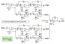
Linkwitz-Riley Electronic Crossover
(1) R = 1 / (2 × π × 1.414 × f × C)
(2) C = 1 / (2 × π × 1.414 × f × R)
(3) f = 1 / (2 × π × 1.414 × R × C)
Where R = resistance in Ohms, π = 3.14159, 1.414 is √2, f = frequency in Hertz and C = capacitance in Farads
Read here for more details
Linkwitz-Riley Electronic Crossover
Hello Dotneck,
The issue is that real in-box-loudspeaker (e.g. a 6.5"midwoofer) do ussualy not not have a flat response, but are subject to a rising response baffle step) that should be compensated by the filter. Furthermore, peaks need to be notched out. Filter and loudspeaker should be seen as one system: only the final acoustic response counts and that should be textbook: e.g. BW3, LR4 etc. etc.
As result, the necessary transfer function of a just the x/o cannot be a textbook filter, that simply can be calculated with basic formulae: in reality the design is much more complicated. Simple calculators do not work.
Attachments
Except it can't be used for anything serious.
The idea of an LR filter is nice in theory, but like @Boden clearly shows, it all depends on the frequency curve and such.
Speaking of Linkwitz, he has a nice summary of filters that are needed for most systems;
Active Filters
Although one still needs to measure the frequency response of the drivers in de cabinet that is being used under multiple angles.
I am more than happy to explain a thing or two after measuring and professional consulting loudspeaker systems for over a decade, but with the current attitude I don't feel like being invited at all.
- Home
- Source & Line
- Analog Line Level
- active crossover PCB