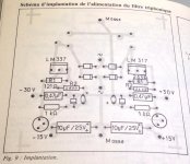
Thanks. Fortunately the link also has a stuffing diagram.
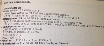
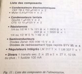
You would definitely want to get your component values
from that.
You would definitely want to get your component values
from that.
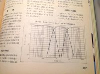
Yes, i plan to verify and recalculate critical cap values, since i plan to use ~150Hz crossover frequency. I will measure exact fr response.
I have few questions about jfets. I do not have K30 or N5465. However, i do have some others. Nelson, please take a look and let me know if any of these could be used.
J103/K246 matched pairs, i got few
Mpf102 got plenty
N4392 few left
N5460/N5457 matched pairs quite a few
Your help if much appreciated.
I ran some sims on the filters, and when I have time I'll post the results.
It's the usual situation, which is that no crossover is ideal for more than
one design - they all have to be tweaked to accommodate the phase and
amplitude response of the drivers.
I did not see in the article what the intended loudspeakers are. Do you
happen to know?
It's the usual situation, which is that no crossover is ideal for more than
one design - they all have to be tweaked to accommodate the phase and
amplitude response of the drivers.
I did not see in the article what the intended loudspeakers are. Do you
happen to know?
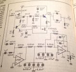
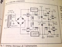
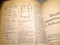
I can't read all the capacitor values. Do you have a better copy?
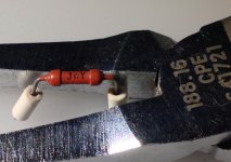
Lucky i get complete " L' Audiophile " paper edition,
funny on bench some vintage resistor made by JOY
Kind regards 🙂
Attachments
-
 B0AFB33B-9B74-4AD3-8C18-F8DACEAD396C.jpg375.1 KB · Views: 808
 -
 794B550E-5823-4A1F-BF54-EAEECB853EB7.jpg201.7 KB · Views: 750
 -
 E41CD9A1-01B9-4114-B7AD-D39A324151C9.jpg342 KB · Views: 763
 -
 7A68F4FD-32A7-44C0-AB8D-4F3A3935F0B0.jpg325.4 KB · Views: 716
 -
 329C5432-49CA-4192-97DF-BA39609774C5.jpg314.9 KB · Views: 362
 -
 BBF888C7-8EB7-455F-AF0C-1546885A0F80.jpg287.3 KB · Views: 316
 -
 9B76DF05-BCF9-48F8-8814-1702C6B67B61.jpg234.8 KB · Views: 341
 -
 CB948CAE-79F4-4DF7-9C28-CC26532C5F74.jpg560.3 KB · Views: 366

I did not see in the article what the intended loudspeakers are. Do you happen to know?
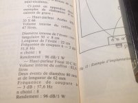
More informations about speakers used with Kaneda active filters are in "L'Audiophile " nr 23
" Little big enceinte "
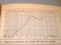
High tweeter | Audax HD 100 D25 BAR
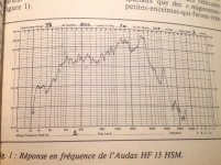
Medium | Audax HF 13 HSM 2CA 12
Low frequence central sub with Audax HD 33 S 66 or another candidate is Focal 10 C 01
Attachments
-
 6A89327D-E18A-4086-8E66-2512A1C7DCAF.jpg510.7 KB · Views: 317
 -
 3B3ADAC3-3497-4598-9BFF-8FB296F924D4.jpg630.4 KB · Views: 270
 -
 355820E6-9097-4F6B-B180-97BB4BA28212.jpg531.8 KB · Views: 198
 -
 E5A87E9C-E22D-4C0F-BDCB-E14F62F67E71.jpg559.1 KB · Views: 213
 -
 08E221A8-66CA-48FF-AEE4-93FC9704F5CB.jpg555.9 KB · Views: 200
 -
 3F01906F-CBAB-4EED-88F9-4EF670BFE8E2.jpg546.6 KB · Views: 212
 -
 D1CE343B-CC64-4532-907F-FB98BB94B79C.jpg386 KB · Views: 194
 -
 D0F6B943-5A97-443A-B444-1D3BA679EF69.jpg384.8 KB · Views: 199
 -
 C0260F90-8AFE-4EAD-B3A9-A1E5A691002C.jpg508.6 KB · Views: 263
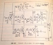
Kaneda 3 way active filter from " Stereo Technic " 1974
Thanks Adason indeed for interesting active filters thread 🙂
Version in Your post #1 was dedicatet originaly for small 2.1 audio system.
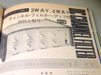
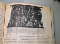
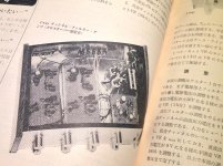
Sunday morning in my library I find Kaneda publication in " Stereo Technic " january 1974
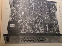
about 3 voice and 4 voice active filters DIY with filters and psu schematics and first prototype builds photo's
Thanks Soundhappy for all the information.
Thanks Adason indeed for interesting active filters thread 🙂
Version in Your post #1 was dedicatet originaly for small 2.1 audio system.
Sunday morning in my library I find Kaneda publication in " Stereo Technic " january 1974
about 3 voice and 4 voice active filters DIY with filters and psu schematics and first prototype builds photo's
Attachments
-
 8BFEA7BD-0191-42CA-88F1-843C9128ED7D.jpg633.5 KB · Views: 504
 -
 2E68F94D-CA3E-4974-933A-5B6BD89FA10C.jpg309.9 KB · Views: 519
 -
 63C0A60B-E3BB-4C2A-8E8D-5A4427BB8B4D.jpg619.2 KB · Views: 514
 -
 F9991463-283D-4F9D-AAF5-E633A6739480.jpg874.8 KB · Views: 494
 -
 FF771DEF-5A8F-471F-9036-421268A6B5AA.jpg278.5 KB · Views: 465
 -
 D817BEBF-9EF7-4B30-BA84-22800300C843.jpg596.4 KB · Views: 277
 -
 FDC9F399-5AB9-46F2-A419-A6C6576BB181.jpg520.2 KB · Views: 293
 -
 E0CDD16C-9EFE-4A6E-843F-D8ADB0DC288E.jpg479.7 KB · Views: 263
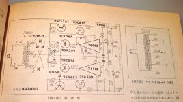
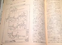
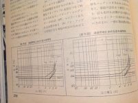
Kaneda 4 way active filter from " Stereo Technic " 1974
Original Kaneda 4 way active filter DIY publication
Original Kaneda 4 way active filter DIY publication
Attachments
-
 8032BCEB-714D-4A82-9A7F-D336012C2175.jpg272.8 KB · Views: 385
 -
 AB838689-029A-434D-999E-A217682FF367.jpg373 KB · Views: 321
 -
 AF402660-B9D9-4A22-BBCC-A0A7931317EF.jpg498.5 KB · Views: 246
 -
 4F561CF7-A0AB-4C19-AA3F-AD5B250CF695.jpg712.4 KB · Views: 263
 -
 F3DA8F0B-342F-44FE-A5E0-F40D87F7436B.jpg514.3 KB · Views: 244
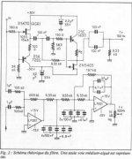
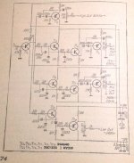
Over in the PL forum I was pointing out that the schematic in the first post
here is interesting because it has two buffer stages, with filter circuits in
between, that use a depletion mode Jfet self-biased with a bipolar transistor.
The first is an N channel Jfet with PNP bipolar and the 2nd is a P ch Jfet with
NPN bipolar. Presumably this was for cancellation of the opposite 2nd harmonic
distortion of both buffers.
I made quick prototype today, and it seems to be working ok. I have not made any measurement, as my equipment is very limited. However, it sounds just fine.
I made few active crossovers with BJT in the past, 2way, 3way, like Soundhappy just posted. Worked ok, just did not sound as good as B1 and JLH buffer based crossovers.
Over in the PL forum I was pointing out that the schematic in the first post
here is interesting because it has two buffer stages, with filter circuits in
between, that use a depletion mode Jfet self-biased with a bipolar transistor.
The first is an N channel Jfet with PNP bipolar and the 2nd is a P ch Jfet with
NPN bipolar. Presumably this was for cancellation of the opposite 2nd harmonic
distortion of both buffers.
Yes, it seems like a well designed circuit.
I guess there should be one more buffer on the output, since it uses one more high pass, to decouple it from next stage...
Hi adason you mentioned JLH buffers. Can you be a bit more specific pls?
I have a lot of JLH schematics and I was wondering which one you were referring to.
I think I recall see both a complimentary BP transitor and a JFet based buffer but am getting forgetful these days......perhaps they were combined......
Grateful for any further enlightenment.
Cheers Jonathan
I have a lot of JLH schematics and I was wondering which one you were referring to.
I think I recall see both a complimentary BP transitor and a JFet based buffer but am getting forgetful these days......perhaps they were combined......
Grateful for any further enlightenment.
Cheers Jonathan
Hi adason you mentioned JLH buffers. Can you be a bit more specific pls?
I have a lot of JLH schematics and I was wondering which one you were referring to.
I think I recall see both a complimentary BP transitor and a JFet based buffer but am getting forgetful these days......perhaps they were combined......
Grateful for any further enlightenment.
Cheers Jonathan
Attachments
Original Kaneda 4 way active filter DIY publication
I'm glad that you are back 😀
- Status
- Not open for further replies.
- Home
- Source & Line
- Analog Line Level
- active crossover Kaneda