Hello!
I've been trying to do an active crossover for a mono speaker, but I seem to be running to a lot of troubles while doing it. I get terrible distortion or the crossover just won't work at all.
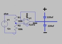
I've simulated it with LTspice, and it works just fine in the simulations. First, I sum the signal from stereo to mono with two 10k resistors (not in picture) + a variable resistor so it is 25k (R5). You can adjust gain by adjusting R3. I have a single-side voltage supply so I have created a virtual ground (bias). From there the summed signal goes to the two filters. The big capacitators at input and output are for blocking DC. 11k at the end is the input impedance of the main stage amp. And before you suggest another OPamp, TL072 is the only one available for me 😛
I've been trying to do an active crossover for a mono speaker, but I seem to be running to a lot of troubles while doing it. I get terrible distortion or the crossover just won't work at all.
I've simulated it with LTspice, and it works just fine in the simulations. First, I sum the signal from stereo to mono with two 10k resistors (not in picture) + a variable resistor so it is 25k (R5). You can adjust gain by adjusting R3. I have a single-side voltage supply so I have created a virtual ground (bias). From there the summed signal goes to the two filters. The big capacitators at input and output are for blocking DC. 11k at the end is the input impedance of the main stage amp. And before you suggest another OPamp, TL072 is the only one available for me 😛
Attachments

I'm wondering if your TL072 has enough power to drive the circuits ground, I would try adding some capacitance between the virtual ground and the +/- rails, 220uf electrolytic caps should be more than enough, this would create a low impedance voltage divider for the AC ground currents and your TL072 would only be setting the DC voltage
Attachments
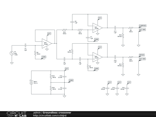
R5 should be duplicated for summing two channels. You don't need extra 10k off board.
Each R5 is a summing input.
The output is { V1/R5.1 + V2/R5.2 + V3/R5.3 + etc. } * R3
If you want the output voltage to be similar to the two individual channels then change R3 to 12k5. Otherwise the output is actually the SUM of the individual channels.
Why are you using 20k & 41k? What Q are you aiming for?
Look at the standard Sallen & Key unity gain filter and compare to the generalised unity gain where each component value can be changed to modify the Q & the F.
The 33ms filter at the output will cut the bass.
Have I quoted the correct Summing formula?
Last edited:
Wrong wrong wrong.
Something like this,
but component values should be calculated - both in crossover and power supply.
Do not decouple the opamp's power supplies to virtual ground... Or not? You will get better distributed capacitance, and nice local decoulpling loops given the VCC-GND supply is stiffier than VCC-VGND and VGND-GND...
Last edited:
Thank you all for replies. I'm looking to get about 2,5kHz 2nd order Butterworth crossover from this circuit.
You don't say what your 'single side voltage supply' is - presumably its not a battery? If its not then your TL072 bias generator might be oscillating due to having a capacitive load from all the stray C in the system as a whole.
The power supply is a stack of li-ion batteries connected in series for about 11.6V total voltage.I'm using 41k and 20k resistors because I scaled the crossover to have 2,2nF capacitators
Last edited:
Who have stacked these batteries? You? Then why wouldn't you use their center point for ground and get +/-5v supply? Everything is easier this way...
Hi Guys, I am building an active crossover for a power amplifier that I am building for a school project. My problem is I am unsure which components to change to give me the crossover frequency I wanted. I am aiming for a x-over at around 200-300 hz, if anyone has any ideas please let me know thanks 🙂
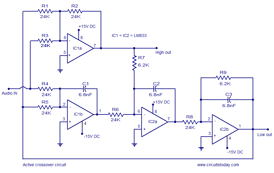
What a strange topology. I'd look at Rod Elliot's 2way project, (and others if you browse his site), he also shows his workings. 😉
It's a subtractive circuit. Not that uncommon, but the high and low pass will not be symmetrical. Advantage is phase preservation.
Thanks pinkmouse but is there anychance you could tell me which values to change as I have this IC to use which is why I chose this particular design. Any help is appreciated
Thanks
Thanks
Thanks SY, I knew it was strange, but vaguely familiar, but didn't have the time to research it. Samp, you can use the LM chip in Rod's designs, or if you search on Google for "subtractive crossover" you may find the required formula.
Once you get it working, check the DC voltage at the output of each opamp.
You may need to add a resistor into the lead from +IN PIN to Ground of each opamp to reduce the DC offsets to manageable levels.
You may need to add a resistor into the lead from +IN PIN to Ground of each opamp to reduce the DC offsets to manageable levels.
- Status
- Not open for further replies.
- Home
- Source & Line
- Analog Line Level
- Active crossover help