This one might seem a bit odd, but bear with me please, I am looking for a schematic for and active crossover for my helper tweeters on my full range system. Currently I am just using a resistor with the regular amp.
It might seem overkill, but I have built some seperate gainclone modules that run on low voltage and are tricked up especially for this application, the problem is I need an active crossover that crosses at about 6500-7000hz range and all the kits etc I've come across are meant for around 3000hz.
I imagine it would be possible to convert an existing kit by changing resistor values but I have no idea how to work that out.
halving the crossover resistors value would double the crossover freq so 3K would become 6K. If you can post a link of a schematic it would be alot easier to tell you what to change.
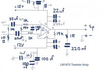
Sample crossover
Sample crossover
sreten said:a simple solution is a high value input coupling capacitor for the amplifier.
Agreed. You don't want a sharp filter with a supertweeter anyways, you'd want a 1st order filter with a very high corner frequency.. That is a job for the coupling capacitor.
EDIT: Unless your setup - without the "helper tweeter" - has sharp premature HF rolloff.
THe fall off isn't sharp and I feel the super tweeter needs to cut in at around 7000hz so what you suggest sounds fine, any suggestions on the type or value to use for the above frequency. It would certainly be a lot easier. Thanks
Zero One said:any suggestions on the type or value to use for the above frequency.
I don't remember much about gainclones but I would presume you have a resistor going from the input signal to ground. This resistor sets your input Z. Determine the capacitance needed by C=1/(2*Pi*f*Z) where f is your corner frequency and Z is the impedance seen by the capacitor. It will return Farads needed, which you multiply with 10^6 to get uF, or 10^9 for nF. As the Z of your gainclone is relatively high, you are looking at a small value wich is good. You would want a quality film & foil cap in this position.
You could even make the crossover adjustable by changing the input resistor with a pot (like a strapped stereo volume pot to adjust both channels simultaneously). Decrease Z, and corner frequency rises - increase Z and it drops. This way you could tune the corner frequency of the filter by ear, to the point where it matches up perfectly.
Good luck!
0 1,
I think making it ear tunable would definitly be worth a try. What you need to do is figure out the lowest likely crossover point, and the highest likely crossover point. Make the Z adjustable within this region plus some margin, for example say you decide 4kHz is the lowest you'd ever want and 16kHz is the highest desirable point, you get:
f1=1/(2*Pi*Zmax*C)=4000Hz
f2=1/(2*Pi*Zmin*C)=16000Hz
Rfixed=Zmin
Radjustable=Zmax-Zmin
C stays the same as it is a fixed value. Choose it depending on what impedance area you want to stay within. Tie the resistor Rfixed (a fixed resistor) in series with the potmeter Radjustable. Ofcourse you don't need an exact value for the pot. Use whatever is closest above your calculated Radjustable. This adjustable series resistor will be what you solder in place of your current input resistors (post a schematic of your clones and I'll tell you which ones).
Regards
- Status
- Not open for further replies.
- Home
- Loudspeakers
- Full Range
- Active Crossover for helper tweeter