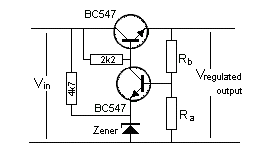
Can I use a circuit like this to bias larger transistors like "2sc2879" into class ab? A pair uses 200ma.
I know I can't run it constantly, but it would be on the relay only on transmission. The idea is to amplify a single side band transmission. The part I don't understand is, when under load will this change or stay pretty regulated? Thanks in advance. I hope I made since to some one.
The voltage will be too much and the base drive circuit should be a very low impedance...see test circuit in pdf.
pdf here:
http://www.datasheetcatalog.org/datasheet/toshiba/1468.pdf
There are better active bias circuits and ALL have temperature feedback from the heatsink...Standard HF class AB power amp biasing.
But I really don't believe that DIYAUDIO is the place for RF SSB amplifier questions.
Better to search on amateur radio circuitry web sites or your local library for ARRL handbooks.
I do not recommend using this circuit.
Good luck.
Thanks for the reply. I've searched and am very active on those forums, however there it's a lot of know how on this site that lacks on those.. or.. it's hard to get secrets out of people. Plus these things are closely related.. I'm doing this part from scratch. Hey.. we all bias them don't we? Lol. I love all things audio and this method will help me in more ways than this. Thanks for the link, I'll check it out and get back to us
Yes I like that one. If I wanted to say, add that to an amp I already built. Class c bias for am.. I used the ferrite transformers with the small ferrite bead to ground on the input and f bead to v+ on the output transformer, could I lift the one on the input and work in that circuitry? Or would I have to do those exact inductor values? I used the popular amp plans floating around online, plus a little ofmy own work.also would I need larger transistors w heat sinks or could I actually use 2222's?
Hey check out the final section on the cobra 148 gtl. It uses a series regulator to bias a 2sc1969. I plugged it into spice and looks ok.. I'm still novice though, im wondering how it would behave under load. It uses 1 Darlington with a diode from base to ground. I used zener in my sim. Worked better.
Thanks for the help man. I've been scratching my head on this for a while!
- Status
- Not open for further replies.