I want to build a 2nd order active bass boost circuit for a boost of 10 dB @ 33 Hz.
I found some schematics, but don't you need a buffer stage of some sort? What about an input and output stage?
I don't know much about building these things, but I have built an active crossover before with step by step procedures. I don't really know how it works exactly so I am kinda flying blind here.
I have the components leftover from another project and I know the values of the resistors and caps. I need. I just need guidance on putting it together.


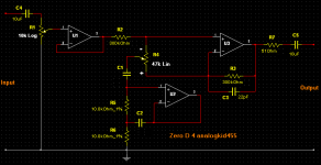
This should achieve what you want. It's a circuit i've modified for you, that i designed for someone else on here last year. Basically it's an Equalizer for one frequency.
33Hz - C1 = 140nf & C2 = 1.4uf
You will probably have to parallel capacitors to get the correct values, or near enough.
U1 - U3 are OpAmps. They could be individual ones, or just using 3 out of a Quad type. I havn't shown the Power Supply connections, as i expect you know how to do that ?
If you need more help, just ask")
33Hz - C1 = 140nf & C2 = 1.4uf
You will probably have to parallel capacitors to get the correct values, or near enough.
U1 - U3 are OpAmps. They could be individual ones, or just using 3 out of a Quad type. I havn't shown the Power Supply connections, as i expect you know how to do that ?
If you need more help, just ask
Attachments
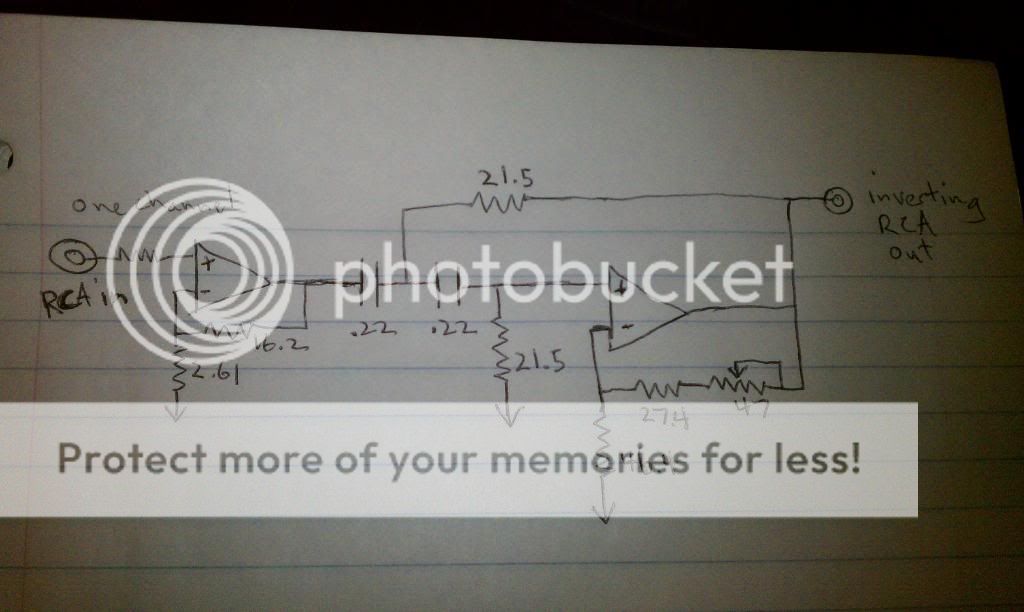
If you get rid of the gain in the first stage and make it a unity gain buffer, the pass band will reduce to about 8dB gain with 18dB total at 33Hz. You might be able to use a voltage divider at the output to reduce it further if necessary, but like I said before, it might be a little noisy.
Mike
Mike
Last edited:
Zero D, Thank you for the circuit! That seems to be alot better than what I came up with. That's all I really need is a 1 band EQ. Would the Q be .5 on that circuit?
Also, I think I know how to hook the power up, but maybe you should tell me anyway. I have a regulated power supply and I think I have to put a .1 cap from the + and - power input, to ground. Is that right? Hmm.
Michael, thanks. So no way around it being noisy? Can you refresh me on how to make it unity gain?
In the end I think I will go with the 1 band EQ.
I said it MIGHT be a little noisy, especially if you knock the gain down with a voltage divider on the output. Doing it that way would end up increasing the noise contribution from the op amps, so depending on which chips are used and what the rest of the signal chain consists of, it could be an issue.
To use an op amp as a unity gain buffer, just connect the output directly to the inverting input (no resistor), and apply the signal to the non-inverting input. In that configuration the chip will amplify current instead of voltage to provide a buffering function.
Mike
To use an op amp as a unity gain buffer, just connect the output directly to the inverting input (no resistor), and apply the signal to the non-inverting input. In that configuration the chip will amplify current instead of voltage to provide a buffering function.
Mike
Pleasure !
I missed you wanted Q = .5 so i've changed a few things. C1 & C2 = 470nf & i've also made R2 & R3 = 43K
If you use single OpAmps + Supply goes to Pin 7 - Supply goes to Pin 4
If you use dual OpAmps + Supply goes to Pin 8 - Supply goes to Pin 4
If you use quad OpAmps + Supply goes to Pin 4 - Supply goes to Pin 11
Yes a .1 cap from the + and - power input to ground is a good idea, as are a 10uf electrolytics in the same positions. Your regulated supply should be + & - 12 to 15 volts DC.
- Status
- This old topic is closed. If you want to reopen this topic, contact a moderator using the "Report Post" button.
- Home
- Source & Line
- Analog Line Level
- active bass boost