For some reason I'm not getting email notification of new posts to this thread. Strange, since I've posted to it a couple of times 
Well, I should receive them now.
Ron
Well, I should receive them now.
Ron
This thread have been asleep long enough 🙂
Did anyone manage to build an absorber based on Nelson's Shadows? What was your experience?
At this side of the Atlantic we are currently trying...
But since the discussion on that forum is in Swedish, you probably only can enjoy the pictures.
So far we have got a circuit diagram and PCB layout. You can find it in this thread:
http://www.hififorum.nu/forum/topic.asp?TOPIC_ID=70570&whichpage=12
Look at the post done 2009/09/25 : 21:37:46 There you find links to schematic, PCB and component list.
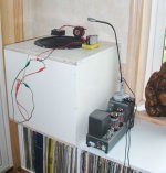
One prototype absorber have been built from this. It's in action on page 15.
http://www.hififorum.nu/forum/topic.asp?TOPIC_ID=70570&whichpage=15
It wasn't me who built that one, so I can't take credit for it.
I include a picture from first test run here as teaser, it's true DIY style:
Did anyone manage to build an absorber based on Nelson's Shadows? What was your experience?
At this side of the Atlantic we are currently trying...
But since the discussion on that forum is in Swedish, you probably only can enjoy the pictures.
So far we have got a circuit diagram and PCB layout. You can find it in this thread:
http://www.hififorum.nu/forum/topic.asp?TOPIC_ID=70570&whichpage=12
Look at the post done 2009/09/25 : 21:37:46 There you find links to schematic, PCB and component list.
One prototype absorber have been built from this. It's in action on page 15.
http://www.hififorum.nu/forum/topic.asp?TOPIC_ID=70570&whichpage=15
It wasn't me who built that one, so I can't take credit for it.
I include a picture from first test run here as teaser, it's true DIY style:
Attachments
It's really not that hard to do - I'm a little surprised that this
hasn't been tackled by DIYers in the past.
😎
hasn't been tackled by DIYers in the past.
😎
It's time for a bump again!
Years ago Mr Pass was kind enough to post information about the Shadows on Pass Labs website. Seems those things are removed.
But He is still kind enough to allow the information to be made public
Link to: Shadow product brochure
Years ago Mr Pass was kind enough to post information about the Shadows on Pass Labs website. Seems those things are removed.
But He is still kind enough to allow the information to be made public
Link to: Shadow product brochure
During last winter, more work have been done. Resulting in schematics, a PCB and experiments.
The schematics have been upgraded with a Linkwitz filter to get better low frequency property.
The schematics have been upgraded with a Linkwitz filter to get better low frequency property.
Attachments
The patent claims a 20-200 hz effective response,is that just due to the shallow 1st order roll off allowing it to still be effective that low?The production piece had a single pole rolloff above about 100 Hz and below about 70 Hz,
This looks interesting and I want to give it a try with a pair of 8" woofers that I have on hand.Their response in a sealed box begins to roll off below about 65hz,should I add still provide a single pole hi pass filter at 70 hz?
The rolloffs are there to keep the system stable, since the
phase of the loudspeaker/microphone combination varies
enough to cause oscillation (motorboating) with higher amounts
of feedback over a wider band.
As it is, only a little feedback is required for it to be very
effective.
😎
phase of the loudspeaker/microphone combination varies
enough to cause oscillation (motorboating) with higher amounts
of feedback over a wider band.
As it is, only a little feedback is required for it to be very
effective.
😎
An example about the Linkwitz part. It complicates the design, and those who don't like it can skip some components to get a flat response.
Why was it introduced?? Hmmm... A long and cold winter 😀
Why was it introduced?? Hmmm... A long and cold winter 😀
Attachments
Thanks Nelson.
So heres my plan.Use a single down firing 8" woofer(similar to bottom section of the shadow) in each of the front corners.Unless having the dual woofer set up like the shadow in one corner is deemed to be better?
The electonics will consist of
1)an input buffer for the Panasonic mic element.
2)a single pole 70hz hipass filter.
3)a single pole 100hz lowpass filter
4)invertor stage.
5)gain control
6)Chip amp.
Should I proceed on this course?
Thanks Nelson.
So heres my plan.Use a single down firing 8" woofer(similar to bottom section of the shadow) in each of the front corners.Unless having the dual woofer set up like the shadow in one corner is deemed to be better?
The electonics will consist of
1)an input buffer for the Panasonic mic element.
2)a single pole 70hz hipass filter.
3)a single pole 100hz lowpass filter
4)invertor stage.
5)gain control
6)Chip amp.
Should I proceed on this course?
That's pretty much what I did. Using the dual woofers and
placing it in a corner gets the most effect, as corners are
where the resonance pressure builds up the most, and this
way you hit two corners with one unit.
😎
Thanks Nelson ,the reply is much appreciated.
To clarify I may build 2 single woofer units and place them in different corners.
To clarify I may build 2 single woofer units and place them in different corners.
Any one build those ?
any pictures ?
Would like to build some but more compact size, to be place in the corner.
any pictures ?
Would like to build some but more compact size, to be place in the corner.
post 44, 45 etc was based on misinformation. I apologize!!
Just forget that schematic and the EQ section, it does not work as intended.
If you want to extend the fs to lower frequency, do a coating of the element to stiffen the membrane specially close to the interface between membrane and voice coil interface.
The phase margin after the filters was ruined... and as a result the open loop feedback was not sufficient enough to create a good absorption!
So... all capacitors in series between the mic and the amplifier output has to be as large that the high pass pole should be less than approx 2 Hz. Or removed completely!
So it is actually much more easy to do than you might think.
Delete the EQ!
Get a mic, place it as close to the speaker element as possible and also close to the center. Cut high frequency above 100-200 Hz.
crank up the volume (feedback) until resonance, and turn the knob down with a couple of dB.
If there is some high frequency tone "hanging" when you knock with the fingers on the cone reduce the feedback little bit more.
To improve the preformance even more build a box out of 1-2 inch rockwool to encapsulate the woofer/mic.
The woofer shall be put in to a closed enclosure and add damping material in that box too.
Place those absorbers in the corner of the room.
- Home
- Amplifiers
- Pass Labs
- Active Absorbers