hello,
I am redesigning my 3way analog active crossover. i am wondering about the negative spike produced when the tweeter is reversed. It is a must? There must be a deep spike at the cross frequencies? according to this design http://www.linearx.com/files/pdf/FilterShopApp_05.pdf the spike on the mid-tweeter cross frequency is not large. So this cross will not sound right? this design is not correct?
How can i find the delay needed (for the tweeter and if needed for the midrange)? i am using REW and umik microphone but i cannot calculate the exact delay. (maybe someone can tell me how because i tried several times without luck)
What do you think about developing the crossover using minidsp 2x4 and changing the delay and measuring with REW so i can find the exact delay needed and then i can use it for the crossover software. (leap)
Last edited:
hello,
I am redesigning my 3way analog active crossover. i am wondering about the negative spike produced when the tweeter is reversed. It is a must?
If you are talking about the step response, then yes, reversing the tweeter will cause the first spike to be opposite of the next driver. What the ideal polarity of your tweeter should be however depends on a number of factors. Crossover frequencies and slope, acoustic behavior of the drivers, physical location across the Z axis.
There must be a deep spike at the cross frequencies? according to this design http://www.linearx.com/files/pdf/FilterShopApp_05.pdf the spike on the mid-tweeter cross frequency is not large. So this cross will not sound right? this design is not correct?
"Spike" usually means going up, not down. Regardless of absolute phase, each peak should mesh with the next one seamlessly.
Reversing a driver should create deep null in the frequency responses with symmetrical sides. This is a good indicator of well matched drivers and crossovers. This also implies smoother frequency response above and below the crossover point as well as better behavior above and below the tweeter axis.
How can i find the delay needed (for the tweeter and if needed for the midrange)? i am using REW and umik microphone but i cannot calculate the exact delay. (maybe someone can tell me how because i tried several times without luck)
Measure the FR of the drivers in the cabinet. First by themselves and together with no crossover. You may need a cap on the tweeter to prevent damage. You'll get a rather complicated FR plot. This is your time signature in a way.
In some simulation tool such as XSim, adjust the delay of the 2nd driver until the frequency response matches the actual response of the two drivers together. THanks to the complex nature of the two drivers working simultaneously, you'll ahve a very easy time matching up the peaks and valleys of the FR. Of course, when properly crossed over this signature will disapear.
Repeat for the next two pairs of drivers. Remember you'll now measure Mid to Woofer distance, so you'll want to add this to the mid to tweeter distance to get the final Woofer distance.
You can also estimate the Tweeter to Midrange distance. Estimate this way:
Mid delay = (Mid range distance between rear of magnet to rear of mid face plate) - (tweeter distance between rear of magnet to rear of tweeter face plate)
This should be a rough guide to how much delay to start with.
If you are using miniDSP, I would consider a digital crossover. Then you can delay your drivers so that they appear to be in the same Z axis, allowing you to have a perfectly time and phase aligned system. Without this delay, a flat speaker baffle can only be perfectly phase aligned, but not time aligned. Of course, many would argue that's all you need.
Good luck!
Best,
Erik
Last edited:
hello again,
so i made three measurements using REW and calibrated umik without any filte in this sequence:
1. tweeter sweep from 500 to 20k
2. midrange sweep from 20 to 20k
3 tweeter and midrange parallel sweep 500 to 20k
the mic position was for the three measurements at tweeter axis 1m distance. i have not moved the mic or the speaker so the phase is captured in those measurements correctly. I used the same gate start (left window=0ms, ref time=-0.3ms, right window=2 or 2.5ms) point on those measurements and the i extracted to text files (using 48db smoothing) so the can be imported to lspcad or similar software.
i am uploading those files . Can someone please help me? I mean someone that can handle the lspcad or similar software to import those measurements and find the Z distance of the midrange? I tried to do it but i can't get the predicted response same as the real one (tw+mid).
the midrange driver is exactly 175mm (Y=-175mm) below the tweeter and they are on the same X axis. The tweeter baffle is about 21mm behind the midrange baffle but i need to find the midrange Z exactly. There is a good chance for the midrange Z to be zero.
Attachments
hello again,
so i made three measurements using REW and calibrated umik without any filte in this sequence:
1. tweeter sweep from 500 to 20k
2. midrange sweep from 20 to 20k
3 tweeter and midrange parallel sweep 500 to 20k
the mic position was for the three measurements at tweeter axis 1m distance. i have not moved the mic or the speaker so the phase is captured in those measurements correctly. I used the same gate start (left window=0ms, ref time=-0.3ms, right window=2 or 2.5ms) point on those measurements and the i extracted to text files (using 48db smoothing) so the can be imported to lspcad or similar software.
i am uploading those files . Can someone please help me? I mean someone that can handle the lspcad or similar software to import those measurements and find the Z distance of the midrange? I tried to do it but i can't get the predicted response same as the real one (tw+mid).
the midrange driver is exactly 175mm (Y=-175mm) below the tweeter and they are on the same X axis. The tweeter baffle is about 21mm behind the midrange baffle but i need to find the midrange Z exactly. There is a good chance for the midrange Z to be zero.
Maybe I misunderstood. Is this speaker using a flat baffle, or a stepped configuration? If flat, no way midrange can be zero. 🙂
Here. Convert your files to FRD and use XSim.
http://www.diyaudio.com/forums/multi-way/259865-xsim-free-crossover-designer.html
FRD has no headers. Column1 = frequency, 2 = DB level, 3 = phase (optional).
Separate the columns by tabs and make sure your numbers do NOT include commas. Digits and "." only.
Best,
Erik
hi
thank you for your help.
Yes this speaker is stepped baffle configuration. The mid is behind the woofer and the tweeter is behind the midrange on Z axis. When i first made tose speakers they had a passive crossover. Now i need active crossover for them.
thank you for your help.
Yes this speaker is stepped baffle configuration. The mid is behind the woofer and the tweeter is behind the midrange on Z axis. When i first made tose speakers they had a passive crossover. Now i need active crossover for them.
Attachments
Hi Ioannaidis
I simulated your "tweeter" and "mid" as a total graph, and the "mid-tweeter" as a reference : the smoothest overlap in the region of 1K to 5K (presuming the xo point fall in this region) is with -22mm Z-offset for the tweeter. I assumed -150mm Y-offset for the mid.
Simulation with LspCAD.
Hope this helps.
hello Draki,
i tried to use the lspcad and imported those data. the closest possible overlap i have when the midrange Y=-175mm and the midrange Z=0mm.
i tried yours suggestion of Y=-150 and tweeter Z=-22 also but without any good results. Maybe you have not checked the simulation distance it must be 1m and no infinite.
Erik squires i cannot find where i can change the driver position in the Xsim software.
Attachments
Flattest overlap with distance set to 1 m (range 1,5K to 5K):
Mid (X=0, Y=-175, Z=0)
Twt (X=0, Y=0, Z=-7)
Mid (X=0, Y=-175, Z=0)
Twt (X=0, Y=0, Z=-7)
hello Draki,
i tried to use the lspcad and imported those data. the closest possible overlap i have when the midrange Y=-175mm and the midrange Z=0mm.
i tried yours suggestion of Y=-150 and tweeter Z=-22 also but without any good results. Maybe you have not checked the simulation distance it must be 1m and no infinite.
My suggestions were for a flat baffle. If you are using a stepped baffle then these should be close to zero, since the tweeter, midrange and woofer magnets should be closely aligned.
In either case the tweeter is your reference distance, so in XSim it's always 0. The mid and woofer are measured relative to it. That's key. You are entering relative distances, not absolutes.
Erik squires i cannot find where i can change the driver position in the Xsim software.
Right-click the driver. Select "Tune" Look at "Mod delay" stands for "Modify Delay"
Best,
Erik
Last edited:
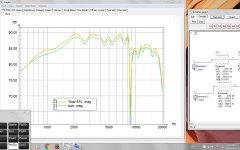
on the graph i posted before the yellow line is the calculated response. the other is the measured response. Are those two responses ok? the only difference i can see is 1-2 db level differences. Can i rely on this software and proceed to calculate the filters with it?
Displaying both graphs, with 1 m distance, Z mid -175 (all others zero), they do look almost identical, the 8-10 KHz range (where the big V-dip at 8700 is) is overlapping, but the rest differs by 1-2 dB.
However, if the tweeter is pulled back by 7 mm (Z tw - 7) then both graphs overlay identically from abt 1KHz up to 7KHz, and that is your range of interest. The previously identical portion from 8 to 11 KHz (where the V-notch is) is now spread apart by 4-5 dB.
So, IMHO, based on your measurements and simulated, the correct Z offset for the tweeter is -7 mm.
What drivers are those? Mid is probably a metal cone (looking at the big peak at cca 10KHz). Tweeter? Some strange looking bumps at 2K1 and 3K3, as if caused by the baffle shape? But I am just speculating.
Yes, the driver is a metal cone the seas excel w15ch001 and the T29cf002. the Z=-7mm means that the tweeter must be delayed am i right? It means that if the tweeter was moved 7mm back then its voice coil centre will be on same z axis with the mid voice coil centre ?
So the tweeter must be delayed about 20uS ? I will be crossing at 2k between those drivers. The mid will be crossed at about 250Hz to the W26fx001 woofer but now i am concerning about the upper range because there is the most phase problems.
So the tweeter must be delayed about 20uS ? I will be crossing at 2k between those drivers. The mid will be crossed at about 250Hz to the W26fx001 woofer but now i am concerning about the upper range because there is the most phase problems.
Yes, the driver is a metal cone the seas excel w15ch001 and the T29cf002. the Z=-7mm means that the tweeter must be delayed am i right? It means that if the tweeter was moved 7mm back then its voice coil centre will be on same z axis with the mid voice coil centre ?
So the tweeter must be delayed about 20uS ? I will be crossing at 2k between those drivers. The mid will be crossed at about 250Hz to the W26fx001 woofer but now i am concerning about the upper range because there is the most phase problems.
If you want to have a time coherent system, where they all start at the same time plane, set the delay in XSim to 0, and look at the frequency signature. Physically move the drivers until the signature matches.
Best,
Erik
Cool thread. I've been working on a similar project.
I'm going to check out xsim, thanks Erik.
At OP, I've been playing around with (Charley Laub's) ACD (active crossover designer) found here: software
Even if you don't use the software, find Jeff Bagby's white paper, I think it's in the FRD Blender page. I enjoyed it, and feel it's very relevant to this time/phase align stuff.
Happy New Year!
If you want quasi transient perfect response and all drivers positive going (no negative tweeter impulse) look at Harsch XO. Towards end of thread Byrtt figured out how to properly implement it in a 3 way. Makes for very realistic piano drums guitar etc. phase is fairly flat and never wraps. Ideal Harsch has 55deg phase at XO frequency otherwise flat.
http://www.diyaudio.com/forums/multi-way/277691-s-harsch-xo.html
http://www.diyaudio.com/forums/multi-way/277691-s-harsch-xo.html
hello again,
so until now i have made a few measurements with the umik calibrated mic. All measurements at tweeter level and at 1m distance.(gated) First tweeter only then midrange only, woofer only and mid+tweeter parallel. Then using lspcad i found the tweeter and midrange Y,Z axis. The lspcad calculated response is exactly the same as the measured one so the distances YZ are correct. Because i was using gated measurements the valid frequencies are above 400hz. Then i used the nearfield midrange and woofer responses and merged the woofer near+far and midrange near+far measurements at the farfield level. I also added the baffle step correction to the near measurements. So far so god. Then using lspcad i made the filters.
Then ,using 2x4 minidsp, i created the same filters so i can hear and measure the results before i make the analog version of the crossover.
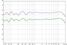
On the picture you can see two curves. The purple one is the total frequency response at tweeter level 1m distanse. The green one is with another 2 filters added to the low and mid sections.
I wanna ask you about the curve +-2db variations under the 400hz. They are room resonanses or speakers problem? I dont now because those low frequencies was made using nearfield measurements. So i must leave the filter as the lspcad calculated (the purple curve) or i must add - change the filters so the curve will be more flat? (The green curve has some filters changed.) Both the curves are not gated and 1/3 smoothed.
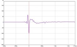
you can also see the impulse response of the speaker. When i invert the midrange the response null are as lspcad calculated. there are -35-40db nulls at the cross frequencies whitch are 230 and 2Khz. I tried different frequencies but at those frequencies the distortions are lower and the overall response better.
I am only concerning about the lower section under 400hz. What will you do?
so until now i have made a few measurements with the umik calibrated mic. All measurements at tweeter level and at 1m distance.(gated) First tweeter only then midrange only, woofer only and mid+tweeter parallel. Then using lspcad i found the tweeter and midrange Y,Z axis. The lspcad calculated response is exactly the same as the measured one so the distances YZ are correct. Because i was using gated measurements the valid frequencies are above 400hz. Then i used the nearfield midrange and woofer responses and merged the woofer near+far and midrange near+far measurements at the farfield level. I also added the baffle step correction to the near measurements. So far so god. Then using lspcad i made the filters.
Then ,using 2x4 minidsp, i created the same filters so i can hear and measure the results before i make the analog version of the crossover.
On the picture you can see two curves. The purple one is the total frequency response at tweeter level 1m distanse. The green one is with another 2 filters added to the low and mid sections.
I wanna ask you about the curve +-2db variations under the 400hz. They are room resonanses or speakers problem? I dont now because those low frequencies was made using nearfield measurements. So i must leave the filter as the lspcad calculated (the purple curve) or i must add - change the filters so the curve will be more flat? (The green curve has some filters changed.) Both the curves are not gated and 1/3 smoothed.
you can also see the impulse response of the speaker. When i invert the midrange the response null are as lspcad calculated. there are -35-40db nulls at the cross frequencies whitch are 230 and 2Khz. I tried different frequencies but at those frequencies the distortions are lower and the overall response better.
I am only concerning about the lower section under 400hz. What will you do?
Attachments
hello again,
so until now i have made a few measurements with the umik calibrated mic. All measurements at tweeter level and at 1m distance.(gated) First tweeter only then midrange only, woofer only and mid+tweeter parallel. Then using lspcad i found the tweeter and midrange Y,Z axis. The lspcad calculated response is exactly the same as the measured one so the distances YZ are correct. Because i was using gated measurements the valid frequencies are above 400hz. Then i used the nearfield midrange and woofer responses and merged the woofer near+far and midrange near+far measurements at the farfield level. I also added the baffle step correction to the near measurements. So far so god. Then using lspcad i made the filters.
Then ,using 2x4 minidsp, i created the same filters so i can hear and measure the results before i make the analog version of the crossover.
On the picture you can see two curves. The purple one is the total frequency response at tweeter level 1m distanse. The green one is with another 2 filters added to the low and mid sections.
I wanna ask you about the curve +-2db variations under the 400hz. They are room resonanses or speakers problem? I dont now because those low frequencies was made using nearfield measurements. So i must leave the filter as the lspcad calculated (the purple curve) or i must add - change the filters so the curve will be more flat? (The green curve has some filters changed.) Both the curves are not gated and 1/3 smoothed.
you can also see the impulse response of the speaker. When i invert the midrange the response null are as lspcad calculated. there are -35-40db nulls at the cross frequencies whitch are 230 and 2Khz. I tried different frequencies but at those frequencies the distortions are lower and the overall response better.
I am only concerning about the lower section under 400hz. What will you do?
It sounds like you are in a medium to small room. A way to test this is to test your speakers outside or in a much larger room, or change the height. Keep the mic in the relative same place. You should see the ripple move around.
I would not worry about the ripple under 400 at all. I'm more concerned above that. How it transitions to 1kHz and the upwards tilting of the tweeter. Since you mention you don't want to discuss, I would say you are fine.
Best,
Erik
hi,
So, you suggest to leave the filters as the lspcad calculate and not trying to lower the low frequency ripples using those filters because they are room resonances?
yes i thought that too.
the room i am trying is about 4x8x3m with speakers at the long side and woofer about 70cm above the floor.
is there anything else to check before really made the analog version? Now i have the opportunity to change and measure using the minidsp.
the gated measurements looks good, phase is ok, sound very good, distortion the lowers possible with those cross frequencies.
this is the second cross design. the first one was built using the 1m speakers responses from the manufacturer and the response and phase are not as good as this one is.
Hah, I was totally right about your room. 🙂 Add some bass traps, and those will go down a lot.
I still don't like the overall balance though, I think your treble should be flat, and maybe 1-2 db below your 300-400Hz level. A bump around 100-400 and a knee to flat around 800-1kHz will sound better I think for a more neutral sounding speaker. However! If you listen at low volumes, then the mid to treble balance is actually pretty good, but the bass will be too low.
Lastly, make sure you start measuring for your intended location as well. If you have been measuring away from the walls, but plan on putting them against a wall or in a corner, now is the time to know how that will change your bass.
Best,
Erik
Last edited:
- Status
- Not open for further replies.
- Home
- Loudspeakers
- Multi-Way
- active 3way crossover phase