Dear diyAudio,
The question is about Electrical Impedance vs Acoustical Power.
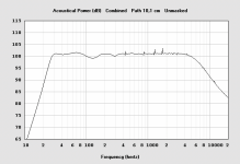
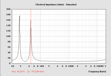
I was able to reach a fairly nice graph for the acoustical power. Then I noticed the worrying behaviour in the electrical impedance. There are two huge peaks, one reaching almost 180 ohms.
What does this mean practically?
Is the Acoustical Power post or pre electrical impedance?
Will there be virtually no sound where the omhs are peaking?
Or, is the impedance accounted for in the acoustical power which would mean I can trust the acoustical power graph?
Many thanks,
Simon
The question is about Electrical Impedance vs Acoustical Power.
I was able to reach a fairly nice graph for the acoustical power. Then I noticed the worrying behaviour in the electrical impedance. There are two huge peaks, one reaching almost 180 ohms.
What does this mean practically?
Is the Acoustical Power post or pre electrical impedance?
Will there be virtually no sound where the omhs are peaking?
Or, is the impedance accounted for in the acoustical power which would mean I can trust the acoustical power graph?
Many thanks,
Simon
Attachments
Simon,
Practically, you need not worry about high impedance peaks.
To make acoustical power, a loudspeaker requires voltage applied to an impedance.
The "Acoustical Power" is representative of the power output given the voltage applied. The level of combined acoustical power at the impedance peaks or troughs are as depicted, given the applied voltage.
You can also look at the excursion minima and maxima, which will be directly related to the impedance minima and maxima.
Above Xmax, output level won't be linear with increased voltage, the simulation becomes inaccurate.
Amplifiers have voltage and current limits, too low an impedance at too high of a drive level will result in clipping or limiting.
Designing for clean, dynamic subwoofer output, best to avoid excursion above Xmax, and impedance below what triggers amplifier current limiting or clipping.
Art
Dear Art,
Thank you for this excellent answer. It relieved my concerns and I will go ahead with the design.
Most of the following information is above my current understanding but it will serve as starting points for digging deeper.
Thank you,
Simon
Thank you for this excellent answer. It relieved my concerns and I will go ahead with the design.
Most of the following information is above my current understanding but it will serve as starting points for digging deeper.
Thank you,
Simon
(Anyone correct me if i'm wrong)
you could also say that the loudspeaker has high efficiency (low current) at the impedance peaks due to resonance.
you could also say that the loudspeaker has high efficiency (low current) at the impedance peaks due to resonance.
Hi Simon,I was able to reach a fairly nice graph for the acoustical power.
the impedance graph seems to me correctly measured and I think I can imagine your setup. But do you have two drivers in your setup? I mean, I have not seen yet a driver with two self-resonances, sharp ones. Please clarify.
Then the acoustical setup needs to be detailed and checked, before conclusions.
Could you describe your setup? I need drivers models, measuring setup (more details about your source), room+miking, measurement software, etc.
Do you also have near-field acoustical phase plots from the mic? Would be helpful.
I would be very interested to help and to follow this topic, for my hobby directions too.
P.S. normally the two resonance peaks means energy stored. This stored energy will dissipate not necessarily into electric energy (= not all this energy will transfer fully to the driver's coil) but rather more to the magnet, to the mechanical parts, etc. I would say, as Weltersys told, that first check is the X_max/SQR(power) at these frequencies and the absolute X_max at maximum (peak) power.
Ionmw,the impedance graph seems to me correctly measured and I think I can imagine your setup. But do you have two drivers in your setup? I mean, I have not seen yet a driver with two self-resonances, sharp ones. Please clarify.
I would say, as Weltersys told, that first check is the X_max/SQR(power) at these frequencies and the absolute X_max at maximum (peak) power.
The impedance and frequency response graphs in post #1 are simulations (not measurements) created in a program called Hornresp:
Hornresp
They are are representative of a low Fs driver in a bass-reflex enclosure with a Fb (Frequency of Box tuning) of around 28Hz.
Although Hornresp provides very good accuracy in most respects, it assumes linear response regardless of the Xmax of a particular driver.
Near and above Xmax, a real driver's output level won't be linear with increased voltage/power, due to Bl (magnetic force in the voice coil gap) and suspension compliance/stiffness variations, so the simulation's SPL level becomes inaccurate when voltage is increased to a level that exceeds Xmax.
Many alignments require far less voltage than the driver can safely handle to exceed Xmax or even reach Xlim (maximum excursion of the driver before physical damage or limitation) which may limit SPL to as little as -10dB the Pe (thermal power handling capacity of the driver)would predict. The driver may "handle" 1000 "watts" without bursting into flames, but hardly gets louder past 100 watts (28.3 volts into a nominal 8 ohm driver).
Art
Last edited:
I see. Thanks!
Nonetheless, if you know a place to see such measurements(!) and eventually their interpretations/analysis, please tell me.
Nonetheless, if you know a place to see such measurements(!) and eventually their interpretations/analysis, please tell me.
I am concerned that there are shown only measurements for horns.
I am interested only for drivers on closed enclosures.
Do you think they will be equivalent?
I am interested only for drivers on closed enclosures.
Do you think they will be equivalent?
Ionmw,
You can simulate most any driver in any cabinet design (closed/sealed, with/without damping material, bass reflex, horn, bandpass, etc.) using Hornresp, and compare in what ways they are different or equivalent.
You can simulate most any driver in any cabinet design (closed/sealed, with/without damping material, bass reflex, horn, bandpass, etc.) using Hornresp, and compare in what ways they are different or equivalent.
Weltersys,
Could I find all equations somewhere, plus the units of parameters? Some of them, I am afraid I do not know. Working blind... not an enjoyable experience.
Could I find all equations somewhere, plus the units of parameters? Some of them, I am afraid I do not know. Working blind... not an enjoyable experience.
The Hornresp program has the equations "built in".
Manufacturer's Thiele/Small parameters must be entered into various fields, have no idea how to do that working blind.
Manufacturer's Thiele/Small parameters must be entered into various fields, have no idea how to do that working blind.
- Home
- Loudspeakers
- Subwoofers
- Acoustical Power vs Electrical Impedance