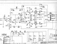
Thanks to those who answered last post, built close to Schematic below but with Antique Sound Lab 5k triode ( No UL taps) OPT XFMR with KT88's. Prior to build had been told by B. Rozenblit that the parallel triode biasing would work, but had miscalculated and told him 300 volts at top of load resistor - it's more like 375, reason for checking was it looked like two of his designs someone else had kludged, and the bare board came with schematic showing 12ax7 R load 270k, BOM showing 470k, board preprinted with 470k and pictoral of board showing 220k ( and 3.3k for Rk as opposed to rest of Rk's = 600R). SO ---( with Ax7 RL 470k, Rk 600R) at 450 B+ ;395 v at top of phase splitter Rload, region of 140 v at Rk(18k), 63 volts at Grid of 12au7. (quiescent). , with CD input get light hum on 8 ohm tap but no actual music out, Good Buzz if you touch the input, and when I chicken out and pull the plug and Caps bleed down I get low volume music for a few seconds .
My calcs/ears show this parallel triode seems to be in cutoff and that I should get Vdrop over 25k dropper down to 355 for 220k load on 12ax7, with about 138 volts out to 12Au7, 362 volts with 118 out for 270k, and 375 volts with 70 out for the 470k ( which of course is what I have in there). The above lower values also move 12ax7 bias up from -0.5 to about -1.0. I am told that when in parallel the two triodes behave as a "new tube" . Which I do not know how to calculate for so maybe all my math is way off.
Why not just plug in a pot and try various R loads for 12ax7 ? because I had the bright idea of vacuum impregnating the mildly humming power transformers and they are taking forever to dry out. Anyone have suggestions best way to calc 12AU7 cathode voltage vs 12ax7 RL and Rk for parallel triode so I can bias this correctly? Thanks in advance.
Attachments
Anyone have suggestions best way to calc 12AU7 cathode voltage vs 12ax7 RL and Rk for parallel triode so I can bias this correctly? Thanks in advance.
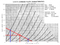
Paralleling up is NBD. Here's an example loadline for one section of a 12AX7. If you wanted to use the other half in parallel, the composite plate load resistor would drop to 100K (200K || 200K). Given the Ipq and Vgk, the cathode bias resistor would be:
Rk= 1.25/0.58E-3= 2155R (2K15 or 2K design nominal)
If paralleling, that would like wise be cut in half (since the current doubles) and a 1K1 cathode bias resistor would work there. Theoretically, paralleling doubles y(f) and halves Rp, so the gain stays the same.
If you've got two 12AX7 sections in parallel, and what looks like a 370K plate load, that's like giving one section a plate load of 740K. It's no wonder they're not passing any signal until you switch off. For a load like that, you'll need a much higher Vpp to get 'em to work at all.
Attachments
Thanks Miles, Using above it looks like I really need 470K plate load and 1000R cathode and then reduce by 50 % for two paralled tubes. I will try it as XFMR's are almost dry. John
- Status
- Not open for further replies.