I got hold of a CD on warehouse clearance, an Eminence ASD1001. It shows some promise of working, possibly:
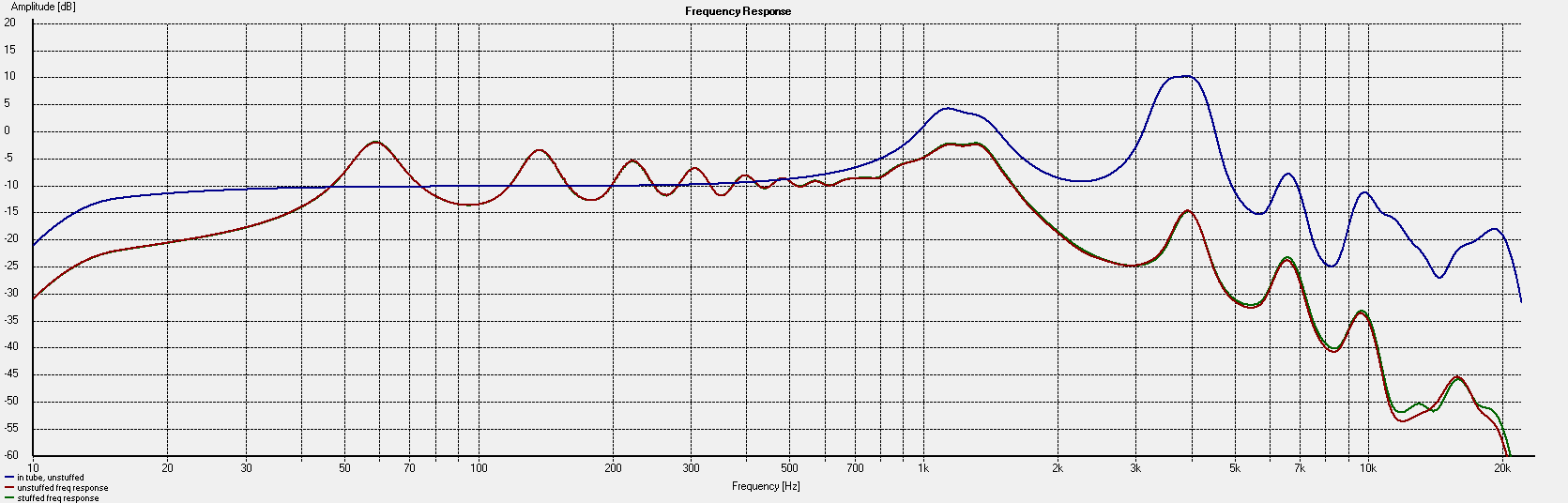
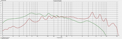
Blue is directly coupled to the CD, Red is via a relatively straight 2m hose, Green is by the same 2m hose coiled.
What I see is treble loss with the hose added. Quite a lot, about 40dB deviation from flat at 20kHz. Coiling seems to make little difference fortunately.
Might I assume 6dB treble loss per doubling of distance in a set up like this? This would mean another ~40dB loss after the desired hose length, or 80dB total. A LOT! But, response to just 10k is more than acceptable. Also considering with this length of hose the mic gets overloaded with less than half signal directly from a soundcard output (no amplifier), then it is possible that this 80dB compensation could be achieved with no more than 1W of amplifier power.
Noise shouldn't be a concern in so much as the huge treble lift will be attenuated acoustically. However, will the delayed noise culminate, meaning that after a period of time noise levels will rise, perhaps continuously!? Or is it assumed that with noise being random, as much of the noise will add constructively as will destructively interfere?
The resonances are a mystery to me as they appear the same both with and without a hose. I thought they were a fuction of the short hose resonance and would dissapear with a long hose, but perhaps not.
Attachments
Acording to your chart you are showing about 25db of loss at 10khz.
This might be able to be compensated with a filter as long as your driver can handle the extra power at those higher frequency's or reduce the power to stay within the power bandwidth limit of your driver.
jer
This might be able to be compensated with a filter as long as your driver can handle the extra power at those higher frequency's or reduce the power to stay within the power bandwidth limit of your driver.
jer
I checked and the power level used to take these measurements was 0.3mW. Leaves some scope for compensation with this 50W driver, but still only 52dB compensation max. Throwing 50W at it is impractical, 1-5W is more realistic, so 35-42dB compensation is a realistic potential.
Bear in mind this 0.3mW produced a level at the mic that was just below clipping. That's a Linkwitz modified WM-61A mic which can handle quite a bit of SPL, but I rather think it is my mixer which clips before the capsule without any padding. Anyhow, the average power level could be reduced, perhaps at the expense of ambient noise levels.
I also don't know how a 170 metre hose will react compared to 2m. Is 6dB per doubling of length the worst case, or is it worse as perhaps the hose walls absorb/damp treble energy too? Want some idea whether it'll be useable before buying a long hose!
Don't know about parallel hoses, it's interesting but the hose is a bit too expensive and bulky to buy two anyhow. With 2 I would make a stereo effect!
Long time I know, but I had a bit of an experiment with this idea again recently. I built a transducer to drive the tube from a small speaker I had on hand:
Visaton - Lautsprecher und Zubehör, Loudspeakers and Accessories
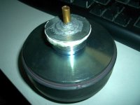
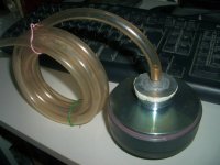
Mounted into a small cylindrical MDF enclosure, with the acoustic output via a 5mm brass tube.
Issue with it is very little treble output.
Your problem is not with the driver per se, but the coupling between the speaker and the tube: the air volume in front of the driver is acting as a low pass filter absorbing the high frequencies before they get to the hose. Compression driver diaphragms are close to their phase plugs for that very reason, as a matter of fact.
You might want to create a phase plug to minimise the gap between the speaker and the tube as a first start, then get more fancy if the urge strikes you.
That's rather interesting. I read over this and have a bit more understanding of it now:
Phase Plugs
However I am now using a compression driver, which has its inbuilt phase plug, but that plug is for a 1" exit. Is there any way I can improve the coupling to the small output tube? Some photos are attached. It is currently just mounted directly over the output with a washer to seal it off.
Attachments
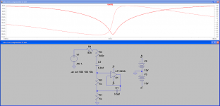
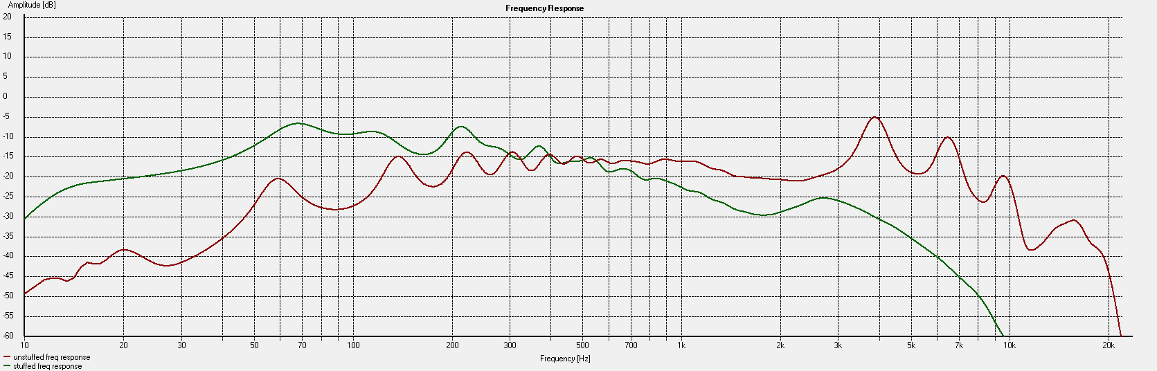
So, I designed and breadboarded a simple compensation circuit for this system. I decided I'd make it bandpass by rolling off the lows by way of a coupling capacitor, which is the safest way to run the compression driver anyhow, also essential with a little LM386 amplifier!
From this I can use a gyrator based notch filter circuit to try to flatten out the response. It works pretty well, save for some low frequency wobbles (presumably tube resonance, wouldn't happen with a long tube) and high frequency peaks which remain a mystery to me but arn't as audible as you'd think.
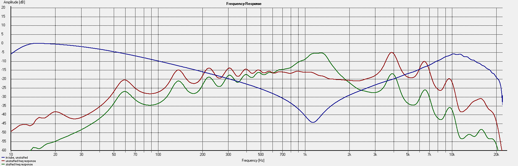
*Blue = Electrical compensation circuit response
*Green = Un-compensated response including high-pass/cap coupling
*Red = Compensated response
The high frequency peaks could be compensated at the microphone end as applying attenuation of high frequencies at the microphone end is preferable to doing so at the driver end; they may be resonances but they're efficient transmission of precious high frequencies . Notice that accross the 'telephone band' (300-3kHz) response is good. I want 100-10kHz though, with filters for reducing the bandwidth as desired.
As promising as this looks, I don't know what will happen when that tube, which is about 2.5M, is extended to 170M . It simply may not be feasible, this seems near the practical limit for compensating it.
From this I can use a gyrator based notch filter circuit to try to flatten out the response. It works pretty well, save for some low frequency wobbles (presumably tube resonance, wouldn't happen with a long tube) and high frequency peaks which remain a mystery to me but arn't as audible as you'd think.
*Blue = Electrical compensation circuit response
*Green = Un-compensated response including high-pass/cap coupling
*Red = Compensated response
The high frequency peaks could be compensated at the microphone end as applying attenuation of high frequencies at the microphone end is preferable to doing so at the driver end; they may be resonances but they're efficient transmission of precious high frequencies
. Notice that accross the 'telephone band' (300-3kHz) response is good. I want 100-10kHz though, with filters for reducing the bandwidth as desired. As promising as this looks, I don't know what will happen when that tube, which is about 2.5M, is extended to 170M
. It simply may not be feasible, this seems near the practical limit for compensating it.Attachments

The problem with acoustic delays are many including inadequate output, irregular FR, resonances. Why not try a tape delay instead. With opean reel analog tape recorders pretty much out of favor you should be able to get them fairly cheaply used on e-bay. Head spacing and tape speed are the variables and at 3 3/4 ips you should be able to get the delay you want with about a 2" space between the record and playback head and still get decent FR and S/N ratios with low distortion. 1 7/8 ips will give longer delays with some loss of hf output.
There certainly are numerous issues with the acoustic delay! I didn't realise they were something which was ever commercially made or sold? If you have any info/specs on some commercial units I'd like to see them!
Tape delays are cool too and can give some interesting effects. I'm not after a perfect delay effect, I have plenty of VSTs for that, so the flaws of the acoustic delay are just part of its uniqueness. Tape delays can sound interesting though with thier wow and flutter and the degrading of quality as it repeats numerous times.
Tape delays are cool too and can give some interesting effects. I'm not after a perfect delay effect, I have plenty of VSTs for that, so the flaws of the acoustic delay are just part of its uniqueness. Tape delays can sound interesting though with thier wow and flutter and the degrading of quality as it repeats numerous times.
Don't kow much about acoustic delays. I'm sure there were attempts at building acoustic reverb rooms that relied on actual room reverberation for their effect but these would have been customized.
I've built tape delay circuits using a mix of both recursive and non recursive delays combining several tape decks. Interesting what you can do with them. If you use a recursive tape delay you have to be careful to keep the heads clean and bias and equalization under control. With each pass, any FR abberation is multiplied.
I've built tape delay circuits using a mix of both recursive and non recursive delays combining several tape decks. Interesting what you can do with them. If you use a recursive tape delay you have to be careful to keep the heads clean and bias and equalization under control. With each pass, any FR abberation is multiplied.
I found this program for audio delay 0 to 30 seconds, seems to work well.
DaanSystems - Radiodelay
DaanSystems - Radiodelay
With the setup that you posted a picture of there will definitely be some acoustic impedance mismatch that won't help with a linear frequency response either.
The tube should be of the same inner diameter as the driver exit. With the reduction that you use (With the washer) you will have an acoustic lowpass filter right at the beginning.
At the other end it is important that you dont have an acoustic mismatch either.
One thing that might also help making the thing work in a more neutral fashion would be putting the whole contraption into a box and fill it up with sand.
Regards
Charles
Yes, this acoustic mismatch is causing treble loss before we even get to any significant length of hose, which isn't helping. I can't use a larger tube as it'd be physically massive to use a 25mm ID hose instead of 4mm! Of course, the hose matches the microphone end in size pretty much ideal (WM-61A capsule).
I don't think a 4mm driver really exists, and if it did, wouldn't have the power to drive a long hose. My original idea was to use ear-canal phones to drive the hose. These would be about an ideal size match, but I can't imagine they have enough power now that I've been experimenting with this.
Is there a way then to reduce the 25mm CD output without such treble loss? Would doing it via a cone help at all, rather than reducing it instantly like with the washer? DSP_Geek made a good post mentioning phase plugs, but the CD already has one designed for its 25mm output. Can I retrofit a second one to reduce it further?
Yes, this acoustic mismatch is causing treble loss before we even get to any significant length of hose, which isn't helping. I can't use a larger tube as it'd be physically massive to use a 25mm ID hose instead of 4mm! Of course, the hose matches the microphone end in size pretty much ideal (WM-61A capsule).
I don't think a 4mm driver really exists, and if it did, wouldn't have the power to drive a long hose. My original idea was to use ear-canal phones to drive the hose. These would be about an ideal size match, but I can't imagine they have enough power now that I've been experimenting with this.
Is there a way then to reduce the 25mm CD output without such treble loss? Would doing it via a cone help at all, rather than reducing it instantly like with the washer? DSP_Geek made a good post mentioning phase plugs, but the CD already has one designed for its 25mm output. Can I retrofit a second one to reduce it further?
Why not try a 4" drive with 4" PVC pipe or flexible plastic hose. This can be found at home improvement stores like Home Depot. Flex hose is commonly used for gas dryer vents. Underground drainage pipe is corrugated and more rigid. PVC pipe is easily cut with a hacksaw and there are lots of fittings which are easily glued with PVC pipe glue.
I expect that'd work quite well, save for some resonances corresponding to that 4" diameter, however 170 mtres of 4" pipe would be massive and expensive! It must be this 4mm fish air line hose or nothing really, even that is relatively large in such lengths.
I thought I'd re-visit my earphone test and take a measurement, so here's a 'ear-bud' phone mounted to the end of the same hose. No compensation and driven directly from my soundcard.
Earphone is in green. Even though this phone is of relatively comparible diameter to the hose, massive treble loss is still observed.
It makes me wonder if a lot of the issue may be the short hose, around 2.5M, giving a big lift to the lower end by means of 1/4 or 1/2 wave resonance? Listening to music through it, it sounds like a bit like being in a small reflective room.
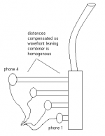
If the earphone had given me much better treble I thought I could use an array of them as shown attached to give more driving power. Unfortunately, it seems not though.
I thought I'd re-visit my earphone test and take a measurement, so here's a 'ear-bud' phone mounted to the end of the same hose. No compensation and driven directly from my soundcard.
Earphone is in green. Even though this phone is of relatively comparible diameter to the hose, massive treble loss is still observed.
It makes me wonder if a lot of the issue may be the short hose, around 2.5M, giving a big lift to the lower end by means of 1/4 or 1/2 wave resonance? Listening to music through it, it sounds like a bit like being in a small reflective room.
If the earphone had given me much better treble I thought I could use an array of them as shown attached to give more driving power. Unfortunately, it seems not though.
Attachments
Back in the day Barry Gordy of Motown used a series of microphones and ampilfiers installed in several attics in the house along the block where the studio was inorder to get echo and reverb effects and also George Martin used a large room full of tuneable pipes and tubes to obtain such effects on the Beatles recording aswell.
Just a few examples of some analog metheds of reverbs and echos.
jer
Just a few examples of some analog metheds of reverbs and echos.
jer
Would doing it via a cone help at all, rather than reducing it instantly like with the washer?
I guess so.
Regards
Charles
Re #35
170 meters is about a tenth of a mile. I'm surprised anything works at all for that length. One way to get a longer delay is to slow down the speed of sound. This can be done by changing the density of air, in short evacuating some of it. You'll have to have both sides of the driver and the microphone within the evacuated closed system so that the air pressure on both sides remains the same. This would allow for a shorter length of larger diameter pipe. A vacuum pump attached with a valve to close the system off once sufficiently reduced pressure has been achieved would allowy you to operate without vibratoins from the pump. There may be a greater loss of gain though. Just a thought.
170 meters is about a tenth of a mile. I'm surprised anything works at all for that length. One way to get a longer delay is to slow down the speed of sound. This can be done by changing the density of air, in short evacuating some of it. You'll have to have both sides of the driver and the microphone within the evacuated closed system so that the air pressure on both sides remains the same. This would allow for a shorter length of larger diameter pipe. A vacuum pump attached with a valve to close the system off once sufficiently reduced pressure has been achieved would allowy you to operate without vibratoins from the pump. There may be a greater loss of gain though. Just a thought.
- Status
- This old topic is closed. If you want to reopen this topic, contact a moderator using the "Report Post" button.
- Home
- General Interest
- Everything Else
- Acoustic delay effect (experimental)