Thanks ,mike, for the reply.
I wiil do some more testing tomorrow as my preliminary test seemed to have fixed the problem.
As you know I am pushing the bias very high (4kv to 6kv) and on two of the panels I have a couple of leaks.
I believe this is what is causing the imbalance.
Adding the resistors allowed the panels to continue to play while the other ones were leaking.
ThIs seemed to stop the charge migration causing of one of them (the one that doesn't leak) to go compleatly dead.
I'll know more tomorrow.
Plus I will take them apart and try to fix the leaks as well.
they all play fine at about 2kv to 3kv but I like the higher voltage as it gives me alittle more efficiancy.
With a single tone test I have approached that of my box speaker if not a little more. jer
Thanks ,mike, for the reply.
I wiil do some more testing tomorrow as my preliminary test seemed to have fixed the problem.
As you know I am pushing the bias very high (4kv to 6kv) and on two of the panels I have a couple of leaks.
I believe this is what is causing the imbalance.
Adding the resistors allowed the panels to continue to play while the other ones were leaking.
ThIs seemed to stop the charge migration causing of one of them (the one that doesn't leak) to go compleatly dead.
I'll know more tomorrow.
Plus I will take them apart and try to fix the leaks as well.
they all play fine at about 2kv to 3kv but I like the higher voltage as it gives me alittle more efficiancy.
With a single tone test I have approached that of my box speaker if not a little more. jer
Ger, what does your bias look like? i'm running 2kv, you have seen the pics as i built mine per Charlie's spec and parts list, can you post a pic, we have discussed this via phone, curious as how they look. pic is worth a thousand words.
Here you go! jer
Attachments
-
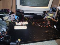 you see I have got put it in a box.jpg64.4 KB · Views: 404
 -
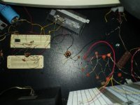 behind the scenes.jpg56.3 KB · Views: 392
 -
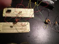 bais supply driver.jpg69.3 KB · Views: 391
 -
 low valtage side.jpg63.3 KB · Views: 382
 -
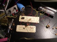
 high voltage side.jpg63.9 KB · Views: 314
 -
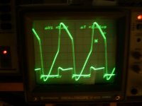 bias drive signal and transformer output.jpg35.6 KB · Views: 146
 -
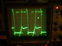 bias drive signal and transformer output full tilt.jpg33.3 KB · Views: 122
Last edited:
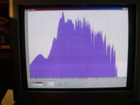
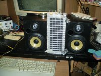
Here is the setup I was working on today.
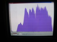
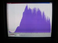
The response pics turned at to be fuzzy,sorry,stupid camera.
All of the test were done with pink noise and exactly the same power level at 1 meter away.
The power level was at aprox 7Vrms or 20Vp-p the equivelent of 6.25 watts into 8 ohms.
The three panel setup matched and exceded the efficiancy of the box speaker by as much as 3db to 6db.
The single panel seemed to measure not much less than 2db to 4db that of the box speaker but matched the efficiancy at the higher end of the frequency spectrum
Again these were just some quick more controled measurements than the ones I have done earlier.
IMO not bad for a little panel.
I will consider these findings in my next small panel build for a desktop setup.
sorry no spl numbers yet but still pretty impressive.
And yes the added resistors solved the imbalance problem.
MY transformation ratio is confirmed at aprox. 1:216 with a 10 turn primary on each core connected in parallel and the four 120v windings in series.
With a 1v peak to peak 500hz signal on the primary and a measured 216v peak to peak across the four 120v series tied windings
Also I had forgot to block off the tweeter in the combined test . jer
Attachments
-
 box speaker pink noise response same power level.jpg38.5 KB · Views: 115
 -
 three panel pink noise response.jpg38.9 KB · Views: 166
 -
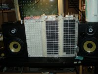 three panel setup.jpg55.7 KB · Views: 204
 -
 single panel setup.jpg65.3 KB · Views: 143
 -
 single panel pink noise response.jpg36.3 KB · Views: 145
 -
 single panel and box pink noise response both same power level.jpg31.7 KB · Views: 96
 -
 behind the scenes.jpg56.3 KB · Views: 118
Last edited:
- Status
- Not open for further replies.