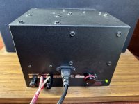
Mike Burgert, who is Roy Esposito's successor doing restoration work on Acoustats, has come up with a new MK-121C interface design. Some photos of his work are shown. If you are interested, go to the Acoustat group on Facebook to find out more.
https://www.facebook.com/groups/167493963322951
Scroll down to where it reads "Coleen Schwartz is with Mike Burgert".
https://www.facebook.com/groups/167493963322951
Scroll down to where it reads "Coleen Schwartz is with Mike Burgert".
Attachments

Last edited:
Newsflash: not everyone is on Facebook, so a private group there is worthless to those that aren't. And you didn't link to the group you're talking about, so I don't know if I'm looking at the right thing. Maybe it's not private. Who knows. I'm one with little patience for the hide-and-seek, guess this, guess that approach to much of anything. I looked, didn't find anything useful, so now I don't care.
Additionally, this feels about like a pretty "girl" on YouTube or a dating site asking users to go to their OnlyFans page or communicate through some other channel.
Carry on.
Additionally, this feels about like a pretty "girl" on YouTube or a dating site asking users to go to their OnlyFans page or communicate through some other channel.
Carry on.
Last edited:
What a pitty (or not...)
I'm totally not interested joining Facebook.
Looks like he changed the circuit for the high voltage supply and makes the high frequency response adjustable from the outside.
OK nice, but not nessecary when you have a good functional standard interface.
Anyway, thanks for posting.
I'm totally not interested joining Facebook.
Looks like he changed the circuit for the high voltage supply and makes the high frequency response adjustable from the outside.
OK nice, but not nessecary when you have a good functional standard interface.
Anyway, thanks for posting.
Looks pretty. Doesn’t look like anything has changed, circuit-wise. Just replaced components with surface-mount. If there’s a demand for replacement boards (because they are defective), this might be a worthy endeavor. Otherwise, I doubt there’s any advantage to this new board if the original is still functioning. I like the detachable mains cord, but this is icing, not a real improvement. Can’t tell how the HF Balance Control is implemented, so will offer no comment.
I tried being the AcoustatAnswerMan on the Facebook Acoustat Group but quickly found the format too frustrating for technical discussions. Conversations can splinter off and too few people read all of them to see if a topic or answer has already been addressed, resulting in a lot of repeated responses. Plus, too many people are primed and ready to argue, so I dropped out of the group. I do this on a volunteer basis (thirty-five years after I left the company) so BS I don’t need. DIYAudio is the best place for me to help Acoustat owners, and here I’ll stay. This is a GREAT group!
I tried being the AcoustatAnswerMan on the Facebook Acoustat Group but quickly found the format too frustrating for technical discussions. Conversations can splinter off and too few people read all of them to see if a topic or answer has already been addressed, resulting in a lot of repeated responses. Plus, too many people are primed and ready to argue, so I dropped out of the group. I do this on a volunteer basis (thirty-five years after I left the company) so BS I don’t need. DIYAudio is the best place for me to help Acoustat owners, and here I’ll stay. This is a GREAT group!

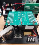
Greetings Acoustat enthusiasts! And Mr. Szabo! I'm the guy who made the boards using SMT. These boards are more than just pretty. The resistors used are MELF types. Not your typical thick or thin film smt resistors. The board design does eliminate all of the through hole components, with the exception of the coupling capacitors, which are also new, and rated at 8kv polypropylene.
By utilizing the MELF resistors, the signal path is no longer 100ft of resistive wire at 0.001" diameter. The low frequency transformer now connects to the stators via precisely made metal film resistors, with a total length of approx 1". They are rated at 1 watt each (x50), but can withstand pulses many times higher. Each resistor is also rated at 350v, so ten of them in series equates to 3500v. They have a temperature coefficient of 50ppm and 1% tolerance. The big wirewounds are 260ppm. The result is much improved low frequency output, along with more revealing midrange.
The high voltage multiplier uses MELF HV diodes, and MLCC caps. The 500M resistor is now five 1w 100M 1W rated at 3kv each, 15kv total. Another advantage to the HV multiplier, is the entire circuit is protected by a baked on HV conformal coating, which prevents any corona activity, and protects the circuit from contaminants and humidity.
The high frequency control also uses the MELF resistors, and a five position rotary switch stepped attenuator, eliminating the slide resistor. In the case of an interface needing the C-Mod, the 10 ohm 48w resistor is built into the design.
Both of these boards offer a significant improvement in sound quality. As many of the older through hole parts are becoming harder to find, more expensive, and even obsolete, I thought the board design was a worthwhile endeavor. The sonic improvements were the icing on the cake, and exceeded my expectations...
I welcome any comments or criticisms!
-Mike Burgert
- Home
- Loudspeakers
- Planars & Exotics
- Acoustat new interface design!