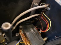
Based on these pics of my MK-121-2A, can anyone tell me if this is unmodified? Also, looking at the 3rd pic with the strip with options to connect to red, orange, and yellow wires, what are these options for? It is currently wired to the middle/orange tap.
Attachments
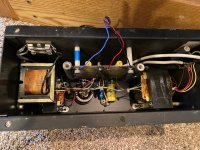

As far as I can see that interface is unmodified.
The colored taps are for the particular model of speaker that you have, red is for model 2, orange for model 3, and yellow for model 4.
Take care,
Doug
The colored taps are for the particular model of speaker that you have, red is for model 2, orange for model 3, and yellow for model 4.
Take care,
Doug
Your interfaces have the Medallion transformers, which was a very expensive factory-modification. I cannot tell from the photos if the C-Mod has been applied, but that is an easy and inexpensive change. If you have the BLUE Medallion label, you have only Medallion transformers. If you have the RED Medallion label, you have both Medallion transformers AND the C-Mod. If there is no Medallion label, then...you guessed it...you can't tell by the labelling. Of course, it's always possible that the C-Mod was applied aftermarket, rather than using the factory kit. In that case, only inspection of the HF control circuit will reveal if the C-Mod is there. Plenty of information on the C-Mod in the "AcoustatAnswerMan is Here" thread.
Beyond that, I see no "aftermarket" modifications.
Beyond that, I see no "aftermarket" modifications.
This connection allows you to choose the amount of bass equalization by selecting different step-up ratios for the bass transformer.... looking at the 3rd pic with the strip with options to connect to red, orange, and yellow wires, what are these options for?
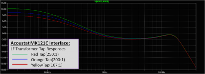
Red = 250:1 (boosts bass about 12dB)
Orange = 200:1 (boosts bass about 10.5dB)
Yellow = 167:1 (boosts bass about 9dB)
For comparison, my recollection is that the CLS interfaces boosted the bass about 7dB.
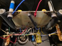
Concerning the C-mod, if you can read the values of capacitors in the middle of your second picture (1 blue, 1 yellow) it should give clear indication if the C-mod has been done.
C-mod will have total capacitance of about 57uF. Non-modded will have total capacitance of about 230uF.
Attachments
Hi guys,
While taking my Model 3s out of storage I noticed one of the red wires snapped off the pin connector. I'm anxious to get these up and running again but I'm unsure how to go about this repair. Can I simply strip and re-solder the wire to the connector? Remove all the wires form the connector and then reattach them all together? Order a new pin connector?
Any advice is greatly appreciated.
You can reuse the pin. Reattach them all together. Heat up the connector and pull out the two remaining taking care to pull out the remainder of the broken one while still molten. They were probably twisted so it will likely slip out with the rest. This is an easy fix.
I have 2 pairs of Acoustat and both pairs work fine but i want
to change all parts in the HV bias circuit.
one pair is a Model 3M having MK-121-2A interface and the second pair
is a Model 3 MEDALLION SERIES having the MK-121-C interface.
Both have same components on this HV bias board,
After some research on the web, its seem better to change the values of 5 HV capacitors from 3300pf
to 4700pf . MOUSER part number: 75-564R30GAD47.
Is it an updated ?
Other MOUSER parts numbers are:
diodes : 583-R5000F-B
500 Mohm Bias resistors: 588-SM104035006FE
I don't see any advantage in changing the stock component values. 3300 pF is fine for the capacitors, and the 500M-ohm resistor is extremely reliable, so unless it's gone off-value (which is very difficult to measure) I would spend my money elsewhere.
The diodes and capacitors do not last forever and replacing them with similar parts is a good idea. Here's some suitable parts I picked out a while ago, not sure if these exact parts are currently in-stock.
Vishay 564R30TSD33 capacitor, 3300 pF, 3000 volts
Mouser p/n 75-564R30TSD33
GP02-40-E3/54 Vishay Semiconductors | Mouser (http://www.mouser.com/ProductDetail...=sGAEpiMZZMtbRapU8LlZD0HbIjlpuZ44XerUncvtHjs=)
In reply to Audio Passion's request, "I have 2 pairs of Acoustat and both pairs work fine but i want to change all parts in the HV bias circuit."
As part of the restoration of my MK-121-2 interfaces, I went through a similar component refresh of all parts in the HV bias circuit.
Please see, "Acoustat Magne-Kinetic Interface MK-121-2 - A Successful Restoration", with details listed in Fig. 6.
https://www.diyaudio.com/community/...ace-mk-121-2-a-successful-restoration.404764/
Figure 6. Step 1, high-voltage ladder components replaced during rebuild (replaced components coloured in blue).
High Voltage Bias circuit – Rebuild
Diodes D1 – D5: 200 mA, 3 kV (R3000FGP-TP, MCC)
Capacitors C6 – C10: 3300 pF, 3 kV, 20% Low-loss Ceramic Disc (564R30GAD33, VISHAY)
Resistor R5: 500 MOhm, 1.5 W, 1% (SM104035006FE, OHMITE)
These components worked well for me, hope this helps.
John

- Home
- Loudspeakers
- Planars & Exotics
- Acoustat MK-121-2A questions