Purpose
.jpg")
Figure 1. Ohmite 10,000 Megohm attenuation resistor.
* This 10,000 Megohm resistor was connected to the input of my Fluke model 289 multimeter of standard 10 Megohm input resistance to provide a simple 1000:1 voltage divider.
Safety precautions with high voltage
* This report follows on from previous reports posted to the diyAudio site:
a) "Acoustat Magne-Kinetic Interface MK-121-2 - A Successful Restoration". https://www.diyaudio.com/community/...ace-mk-121-2-a-successful-restoration.404764/
b) "Acoustat Stator Wire Repair: Hints and Lessons Learned". https://www.diyaudio.com/community/...wire-repair-hints-and-lessons-learned.404881/
* Reason, measured voltages could shift or be unsteady if the high voltage ladder circuit is weak or in need of repair, or stator wires are loose/bent touching the diaphragm.
Test method
* Following figures show examples of wiring connections, and subsequent measurements with the multimeter and Acoustat MK-121-2 interface.

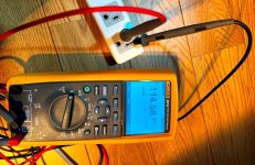
Figure 2. Measured input of Acoustat MK-121-2 interface, 114.5V AC / 50 Hertz.

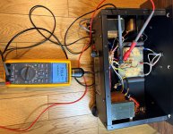
Figure 3. Measured output of bias transformer (input to high voltage ladder) shows 50 Hz, approx. 716V AC.
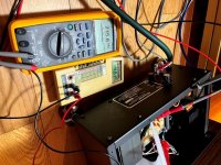
* One end of the 10,000 Megohm attenuation resistor is attached to the red wire terminal at output of high voltage ladder feeding the panel, with other end of the 10,000 Megohm resistor connected to the positive lead of the multimeter - note plastic insulating sheet as a safety caution (Fig. 4). Negative lead of the multimeter is connected to chassis ground.

Figure 4. Measurement shows approx. +5V DC, corresponding to a panel voltage of approx. +5 kV.
* With the Fluke 289 multimeter connected to a Windows PC for data logging, the setup was powered up from cold to observe the time required to reach full voltage (Fig. 5).

Figure 5. Logging of time to reach high voltage.

Figure 6. Example of high voltage stability vs. time.
Final notes
- To share a rudimentary method for monitoring the DC high voltage with my Acoustat Model 2 speakers.
- To record the time required for high voltage buildup, and stability of the high voltage with time.
- While an electrostatic voltmeter is the preferred instrument for measuring DC high voltages, in lieu of an electrostatic voltmeter a simple approximation can be made using a standard multimeter and an ultra-high resistance attenuator.
- 1000:1 voltage divider. For the high resistance attenuation resistor, I used a 10,000 Megohm, 1 Watt, 1% tolerance resistor from Ohmite, part number MOX-750231008FE (Fig. 1).
Figure 1. Ohmite 10,000 Megohm attenuation resistor.
* This 10,000 Megohm resistor was connected to the input of my Fluke model 289 multimeter of standard 10 Megohm input resistance to provide a simple 1000:1 voltage divider.
Safety precautions with high voltage
- Common sense with safety, all connections and disconnections were made with AC power off and high voltage section fully discharged.
- With multimeter leads rated maximum 1,000V DC, to minimize risk of high voltage leakage I placed a plastic foam sheet to insulate the positive (Red) lead from chassis ground (Fig. 4).
* This report follows on from previous reports posted to the diyAudio site:
a) "Acoustat Magne-Kinetic Interface MK-121-2 - A Successful Restoration". https://www.diyaudio.com/community/...ace-mk-121-2-a-successful-restoration.404764/
b) "Acoustat Stator Wire Repair: Hints and Lessons Learned". https://www.diyaudio.com/community/...wire-repair-hints-and-lessons-learned.404881/
* Reason, measured voltages could shift or be unsteady if the high voltage ladder circuit is weak or in need of repair, or stator wires are loose/bent touching the diaphragm.
Test method
* Following figures show examples of wiring connections, and subsequent measurements with the multimeter and Acoustat MK-121-2 interface.
Figure 2. Measured input of Acoustat MK-121-2 interface, 114.5V AC / 50 Hertz.
Figure 3. Measured output of bias transformer (input to high voltage ladder) shows 50 Hz, approx. 716V AC.
* One end of the 10,000 Megohm attenuation resistor is attached to the red wire terminal at output of high voltage ladder feeding the panel, with other end of the 10,000 Megohm resistor connected to the positive lead of the multimeter - note plastic insulating sheet as a safety caution (Fig. 4). Negative lead of the multimeter is connected to chassis ground.
Figure 4. Measurement shows approx. +5V DC, corresponding to a panel voltage of approx. +5 kV.
* With the Fluke 289 multimeter connected to a Windows PC for data logging, the setup was powered up from cold to observe the time required to reach full voltage (Fig. 5).
Figure 5. Logging of time to reach high voltage.
- Again, with the Fluke 289 multimeter connected to a Windows PC for data logging, stability of the high voltage was recorded against time. One example of these time slice recordings is shown in Fig. 6.
- The observed voltage fluctuation was about 1%, although these fluctuations might be due to variation in the input AC line voltage, or noise pickup from exposed test leads with the chassis top cover removed.
Figure 6. Example of high voltage stability vs. time.
Final notes
- This report described a rudimentary method for monitoring the DC high voltage. As a tiny amount of current (typically less than a microamp) will drain through the attenuation resistor and multimeter, there will be some inaccuracy. Nevertheless, the method described can be useful for general measurements, troubleshooting, comparing the performance of one interface vs. another etc.
- From these measurements it was reassuring to see the full high voltage achieved in less than a minute (Fig. 5). This agrees with my observations, these Acoustat speakers play beautiful music and sound fantastic within just a few minutes of powering up.
- A further reward is the sound quality continues to improve over the next several hours, I don't know but perhaps it's because the diaphragm is stabilizing or other factors, as the high voltage shows very stable behavior with time (Fig. 6).
- As mentioned in the two reports, "Acoustat Magne-Kinetic Interface MK-121-2 - A Successful Restoration" and "Acoustat Stator Wire Repair: Hints and Lessons Learned", I purchased these speakers new in 1980, it's amazing that after 44 years they still sound fantastic, as good or better than new.
- And finally, if you try this method, please be respectful at all times of high voltages and take adequate safety precautions.