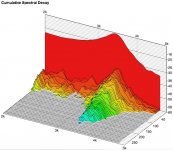
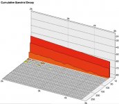
Waterfall of the filtered unit. As you can see, I've even increased the observable threshold up to the noise floor (which is -90dB). There is no significant temporal component. It is at least 40dB below operating level. The waterfall of the notched version looks similar, as the results fall below measurement threshold.
Applying a notch is audible in isolated case, but not anymore when a midrange is added at operating level. The effect is masked.
I.e., the major breakup mode of this rigid cone can be easily prevented by staying away from it, and for the audio-nerd you might even apply a notch.
I would suspect that the "typical" sound as perceived from Accuton units is more than just the rigid cone or breakup effects. For example, a Seas Excel Magnesium cone, or an Usher Berrylium cone reveals very different characteristics from a Thiel, and requires different engineering.
Marc
Attachments
crazyhub said:Hi Marc
I simulated your last Milestones filter posted sept 2 2007 on the dutch forum. Except if my simulation is wrong the break-up peak of the woofer seems to be approximately only 20 db down. Doesn't this peak remain audible?
The average response is about 85dB, the top of the peak is at 47.5dB, so it is more like 40dB down. You can add a resistor of 8.2 Ohms and a capacitor of 0.47uF in series, and put this series circuit in paralllel over the 4.7mH choke, which defines a notch that takes away the peak.
In my opinion this is a theoretical optimization, as to my and others' ears, it is inaudible in a full system (though audible when the woofer is played alone). Implementing the notch this way, also enables high-frequency info to ripple through the woofer as well, as there is a capacitive coupling between the input and the woofer now, but I can't hear that, it is more than 50dB down.
Marc
Semantics
The distortion products are not part of the definition of breakup, they are a consequence of it. Distortion products are created by various means within the driver, yes, including breakup. My point was and is that breakup is linear. Your measurements simply are confirming support since you could not get the CSD results that you show were breakup not linear as you stated. The CSD does not reflect the actual distortion anyway. And since the distortion created by the breakup cannot be separated from the other distortion sources discretely, breakup as a term does not include its contribution to distortion, since distortion is a consequence of breakup.
Of course every driver requires different crossover engineering, that is pretty obvious and should go without saying. However, your example of the low crossover point does not obviate the need for traps in every case. The Seas units that are intended and generally used as mid-woofers cannot be crossed well without them if one is to push the breakup down 30-40db in the stop-band at times. They still don't sound right to me unless they are crossed at about 2K or under and even then are not a match for the best doped-paper units. I believe the problem to be increased distortion (amplification of the non-linear type) even if traps are used.
Dave
Marc wrote:

BTW Shin sure believes I have to change my ears too
I believed 10db between each horizontal line... I have to change my glassesThe average response is about 85dB, the top of the peak is at 47.5dB, so it is more like 40dB down. You can add a resistor of 8.2 Ohms and a capacitor of 0.47uF in series, and put this series circuit in paralllel over the 4.7mH choke, which defines a notch that takes away the peak.
BTW Shin sure believes I have to change my ears too
crazyhub said:BTW Shin sure believes I have to change my ears too
No but I'll certainly have to change mine before I come to the same conclusion as you and marc.
ShinOBIWAN said:
No but I'll certainly have to change mine before I come to the same conclusion as you and marc.
I fully agree!

Marc
Re: Semantics
This gets into the problem of nomenclature..
What is "linear" and what isn't.
To be more specific:
So called "linear" distortion represents no new freq.s/tones. Non-linear distortion describes the *likely* contribution of new freq.s/tones.
In fact both distortion products (with the exception of IM distortion), usually scale in a linear fashion with spl (i.e. higher spls lead to higher levels of distortion, with the inverse also being true). Harmonic distortion is usually time invariant whereas linear distortion is usually time variant - from either perspective one could argue that one distortion is more "linear" than the other. However neither spl or time really fit into the more common definition of what is "linear" or not.
Likewise,
When someone states that their driver is into its break-up region - they are stating that the driver is no longer operating in a "linear" manner. The underlying process is not describing either results of linear or non-linear distortion, but rather the electromechanical process of driving the speaker itself. Technically this process means that the driver is no longer mass controlled in this region (..or at least not in a easily predictable manner). BOTH linear and non-linear distortion is a by-product of driver no longer operating under a typical mass controlled operation. So even if the break-up has a "linear" progression (particularly in time) - it is NOT correct to say that a driver's "breakup is linear".
dlr said:The distortion products are not part of the definition of breakup, they are a consequence of it. Distortion products are created by various means within the driver, yes, including breakup. My point was and is that breakup is linear. Your measurements simply are confirming support since you could not get the CSD results that you show were breakup not linear as you stated. The CSD does not reflect the actual distortion anyway. And since the distortion created by the breakup cannot be separated from the other distortion sources discretely, breakup as a term does not include its contribution to distortion, since distortion is a consequence of breakup.
Dave
This gets into the problem of nomenclature..
What is "linear" and what isn't.
To be more specific:
So called "linear" distortion represents no new freq.s/tones. Non-linear distortion describes the *likely* contribution of new freq.s/tones.
In fact both distortion products (with the exception of IM distortion), usually scale in a linear fashion with spl (i.e. higher spls lead to higher levels of distortion, with the inverse also being true). Harmonic distortion is usually time invariant whereas linear distortion is usually time variant - from either perspective one could argue that one distortion is more "linear" than the other. However neither spl or time really fit into the more common definition of what is "linear" or not.
Likewise,
When someone states that their driver is into its break-up region - they are stating that the driver is no longer operating in a "linear" manner. The underlying process is not describing either results of linear or non-linear distortion, but rather the electromechanical process of driving the speaker itself. Technically this process means that the driver is no longer mass controlled in this region (..or at least not in a easily predictable manner). BOTH linear and non-linear distortion is a by-product of driver no longer operating under a typical mass controlled operation. So even if the break-up has a "linear" progression (particularly in time) - it is NOT correct to say that a driver's "breakup is linear".
Re: Re: Re: Re: Re: Re: Ramblings
I don't think I've ever see that on SL's website (..this of course isn't to say that it isn't there or that he hasn't said this elsewhere).
Moreover SL does (IMO correctly) - heavily caution the level/effects of IM distortion here (under section "G"):
http://www.linkwitzlab.com/frontiers.htm#G
..and here:
http://www.linkwitzlab.com/x-mid_dist.htm
Of particular note is his ranking of drivers (both a non-linear section and a linear one) which includes one Accuton driver.
dlr said:
And consider that Siegfried Linkwitz is of the opinion that IMD levels in piston drivers are not significant enough to be of concern as well, if I recall his position correctly.
..Whatever change in IMD may be introduced by the breakup amplification pales in comparison to the rest of the distortion components in any case. IMD is almost a moot point in piston drivers.
I don't think I've ever see that on SL's website (..this of course isn't to say that it isn't there or that he hasn't said this elsewhere).
Moreover SL does (IMO correctly) - heavily caution the level/effects of IM distortion here (under section "G"):
http://www.linkwitzlab.com/frontiers.htm#G
..and here:
http://www.linkwitzlab.com/x-mid_dist.htm
Of particular note is his ranking of drivers (both a non-linear section and a linear one) which includes one Accuton driver.
Re: Re: Semantics
Yes, but that's not the complete definition.
I captured posts over time at Madisound going back to 2001. The following is from one by Linkwitz. The poster's statements begin with the "=" :
No. Non-linear distortion, as noted above by Linkwitz (HD, IMD or spectral contamination), are BY DEFINITION not scaled linearly by signal level. That's why it's defined as being non-linear.
Linear distortion, noted by the poster and acknowledged by Linkwitz, is a linear function, that is, it does scale with signal level. This includes breakup.
I don't agree with this with one possible exception. Linear distortion is neither time-variant nor signal variant. The exception would be the change in the linear distortion due to motor and voice coil heating making it time-variant for that effect. But for a specific heating of the motor, it will be linear and time-invariant at that point. Non-linear distortion can be time and/or signal variant, but not in a linear fashion. I think Linkwitz's statement is worth repeating:
This is saying that it is a non-linear function of the signal level. Linear distortion, again, does not vary as a function of signal amplitude.
No. When a driver is in breakup, someone may say what they want, but the definition of linear is signal-invariant and non-linear is signal-variant. Breakup is linear by definition. Breakup may amplify any signals already present (linear distortion) and it may amplify signals not present in the original, added by the various distortion mechanisms (non-linear), but the breakup does not introduce non-linear distortions.
In reading Linkwitz's site again, he makes that case for the non-linear distortions being almost exclusively motor and spider related. His discussion never touches on the breakup being so.
Go to this the link to Linkwitz's site below, at the top, section M.
Linkwitz on Linear distortion
Note these sentences (emphasis mine):
Breakup is one or more resonances. Equalization, possible for breakup as well as in the pass-band, would not be possible were it not linear.
I would also direct you to section J at Linkwitz's site. The first line reads:
This is directly relating IMD primarily to motors, not breakup, being the source of most IMD.
Dave
ScottG said:
This gets into the problem of nomenclature..
What is "linear" and what isn't.
To be more specific:
So called "linear" distortion represents no new freq.s/tones. Non-linear distortion describes the *likely* contribution of new freq.s/tones.
Yes, but that's not the complete definition.
I captured posts over time at Madisound going back to 2001. The following is from one by Linkwitz. The poster's statements begin with the "=" :
by Linkwitz in a reply dated 5/29/2001
= Nonlinear distortion implies the generation of
= frequency components that do not exist in
= the original signal. This can occur without
= any energy storage.
= Linear distortion implies that only frequency
= components in the original signal are
= present in the output of the system with
= distortion, but that the phase and magnitude
= may be different. I believe that this also
= implies the existence of energy storage
= (although I am not positive about this).
= Both harmonic and intermodulation are nonlinear
= distortions, I believe that SL considers
= frequency response error typical of linear
= systems to be linear distortion. If I'm
= incorrect, then I hope someone will correct
= me.
= Any basic undergraduate text on either circuit
= theory, network theory, signals and systems,
= or linear algebra should define and discuss
= linearity at length. Distortion does not
= imply non-linearity, although.
= John
This is correct.
Stored energy is just one form of linear distortion, as is frequency response or waveform distortion. Linear distortion is independent of the signal amplitude used for the test.
Non-linear distortion is, by definition, a function of signal amplitude. Harmonic distortion, intermodulation distortion or spectral contamination are all related measures for characterizing non-linear signal handling.
In fact both distortion products (with the exception of IM distortion), usually scale in a linear fashion with spl (i.e. higher spls lead to higher levels of distortion, with the inverse also being true).
No. Non-linear distortion, as noted above by Linkwitz (HD, IMD or spectral contamination), are BY DEFINITION not scaled linearly by signal level. That's why it's defined as being non-linear.
Linear distortion, noted by the poster and acknowledged by Linkwitz, is a linear function, that is, it does scale with signal level. This includes breakup.
Harmonic distortion is usually time invariant whereas linear distortion is usually time variant - from either perspective one could argue that one distortion is more "linear" than the other. However neither spl or time really fit into the more common definition of what is "linear" or not.
I don't agree with this with one possible exception. Linear distortion is neither time-variant nor signal variant. The exception would be the change in the linear distortion due to motor and voice coil heating making it time-variant for that effect. But for a specific heating of the motor, it will be linear and time-invariant at that point. Non-linear distortion can be time and/or signal variant, but not in a linear fashion. I think Linkwitz's statement is worth repeating:
Non-linear distortion is, by definition, a function of signal amplitude.
This is saying that it is a non-linear function of the signal level. Linear distortion, again, does not vary as a function of signal amplitude.
Likewise,
When someone states that their driver is into its break-up region - they are stating that the driver is no longer operating in a "linear" manner. The underlying process is not describing either results of linear or non-linear distortion, but rather the electromechanical process of driving the speaker itself. Technically this process means that the driver is no longer mass controlled in this region (..or at least not in a easily predictable manner). BOTH linear and non-linear distortion is a by-product of driver no longer operating under a typical mass controlled operation. So even if the break-up has a "linear" progression (particularly in time) - it is NOT correct to say that a driver's "breakup is linear".
No. When a driver is in breakup, someone may say what they want, but the definition of linear is signal-invariant and non-linear is signal-variant. Breakup is linear by definition. Breakup may amplify any signals already present (linear distortion) and it may amplify signals not present in the original, added by the various distortion mechanisms (non-linear), but the breakup does not introduce non-linear distortions.
In reading Linkwitz's site again, he makes that case for the non-linear distortions being almost exclusively motor and spider related. His discussion never touches on the breakup being so.
Go to this the link to Linkwitz's site below, at the top, section M.
Linkwitz on Linear distortion
Note these sentences (emphasis mine):
, which is then gradually released. This is a linear phenomenon and in theory can always be corrected with equalizing filters. Thus, the Q of the electro-mechanical resonance, which determines the low frequency roll-off of a loudspeaker, is usually controlled or corrected during the design of the speaker. Equalization may become difficult or impractical in the high frequency region of a driver's operating range.[/QUOTE]Mechanical and electro-acoustic systems often have resonances and thus store energy
Breakup is one or more resonances. Equalization, possible for breakup as well as in the pass-band, would not be possible were it not linear.
I would also direct you to section J at Linkwitz's site. The first line reads:
Drivers are now available that generate very low intermodulation distortion, because their motor behavior is very linear.
This is directly relating IMD primarily to motors, not breakup, being the source of most IMD.
Dave
Hmm,
I think you missed my point.
Which were:
1. Whats the common definition in context for Linear distortion:
Answer:
Distortion that does not include the presence of new tones.
2. Whats the common definition in the context of Non-Linear distortion:
Answer:
Distortion that *does* include the presence of new tones.
3. Whats the common use for the word "break-up region" in context:
Answer:
The upper passband of a driver that no longer maintains an easily predictable mass controlled character.
4. That "Linear" as a word encompasses many uses. It does not necessarily mean a 1:1 relationship.
Again, increasing the input level increases non-linear distortion - that in itself implies some linearity. The "linearity" of linear distortion more closely accords with that 1:1 relationship, or as SL describes it: "is independent". Of course that isn't entirely correct - a linear distortion (such as stored energy) can in fact be increased with input level in a manner that is not 1:1. Additionally, Linear distortion could also be viewed as "dependent" in that its "volume" scales with input level. (I.E. a deviation in freq. response will increase in "volume" with an increase in input level.. but will *less* likely *alter* with an increase in input level.)
This further highlights why we use the above definitions in the context of loudspeakers - otherwise confusion ensues.
Also note that "Distortion" (as used in the answers above) is ONLY limited by the inclusion of the possibility of new tones. In other words when I stated:
""linear" distortion represents no new freq.s/tones."
It was intended that linear distortion includes a number of different distortion products - its just that those distortion products are limited by the exclusion of new tones (..with the inverse true in most instances for Non-Linear distortion).
..............................................................
I'll skip the "time variant vs. time invariant" issue (its interesting, but I'm a bit tired of typing now).
..............................................................
Finally you stated:
"When a driver is in breakup, someone may say what they want, but the definition of linear is signal-invariant and non-linear is signal-variant. Breakup is linear by definition. Breakup may amplify any signals already present (linear distortion) and it may amplify signals not present in the original, added by the various distortion mechanisms (non-linear), but the breakup does not introduce non-linear distortions."
Again thats *one* definition on what is and is not "linear".
It is not correct in the context of drivers and their "break-up" region to use the phrase "breakup is linear" (..at least in most circumstances). EX. - Traditionally, one does not say:
"my driver's break-up is linear" - UNLESS they are inferring that that the driver's break-up region behaves in a more controlled and predictable manner that is similar to its mass controlled region.
Insisting otherwise does NOT aid in communication (however correct it might be from your perspective), but rather confounds those you are trying to communicate with. In fact even prefacing your statement to inform your reader that you intend for a different meaning can (and often does) still lead to miscommunication.
As to the break-up region being solely a linear distortion. I don't "buy" it. Moreover I don't think any reasonable person would either. Nor do I think that either of the statements you have quoted from SL fully support it.
For instance SL's:
"Drivers are now available that generate very low intermodulation distortion, because their motor behavior is very linear."
This only suggests that a very linear motor can reduce the presence of IM distortion. NOT that the motor or the suspension is the SOLE (or even primary) reason for IM distortion for any particular passband for a driver.
The fact is that most drivers that have a high/narrow "q" break-up resonance - usually have non-linear distortion artifacts that are higher in amplitude than difference between the freq. deviation at resonance and the average (non-break-up region).
Just perusing the 6.5 inch driver listing on Zaphs site highlights this.
http://www.zaphaudio.com/6.5test/compare.html
That alone is FAR more "proof" to me that your statement is incorrect (especially when compared to the "proof" you have offered). Admittedly though, neither is really "proof" - and yes, I will concede that you could in fact be correct, BUT at this time I'll hold to my position.
Ah well, interesting subject matter - but its time for me to "bow out".
Re: Re: Re: Semantics
Well... Again this is a matter of how you would mathematically observe this. If I have a signal A.sin(wt + f(t)), it is a function of signal phase, and not a function of signal amplitude. It can be described as a function of signal amplitude as well, by applying goniometry, and it will reveal itself as a frequency component in the spectrum.
What Linkwitz means is that in a linear system amplitude and phase are related, and can be mathematically reated by means of a Hilbert transform. This implies that the measured phase of a speaker and the minimum phase of the speaker calculated from it frequency response should be the same. Although this is a practical assumption for speaker design (because you want to use your speaker unit as a linear device), it is not completely true.
Another way of looking at a linear system F, is in terms of their linear properties superposition and scaling:
1. F(x(t)+y(t)) = F(x(t)) + F(y(t))
2. a.F(x(t)) = F(a.x(t))
These are exactly the conditions under which Hilbert transforms are possible (one can exchange a multiplication and an integral, as the multiplication is with a constant).
If Linkwitz syas non-lineairity is a function of amplitude only, it is easy to misinterpret. Harmonic distortion also creates new frequency components, and hence is a function of amplitude only.
Back to breakups. Considering in isolation the reflection of a wave propagation against a rim is ofcourse a linear property, as it can be described by superposition. That's in essence the core of your message. But...
Feeding any frequency > the primary breakup frequency of my speaker, would cause the primary breakup frequency component to appear in the spectrum. This behaviour cannot be described by means of a linear function.
For non-linear distortions to appear, you need the interaction of an active element. Passive elements (in their ideal form) are not able to create non-linear distortion by themselves. If after exiting your speaker with an impulse, it would directly after that be disconnected from its motor, it would behave perfectly linear as described in your arguments.
Ofocurse, the motor system (well, depending on the definition the amplifier, well, depending on the definition the power plant, well, depending on the definition the burning of oil, well, etc. etc.) --> read some active element is required for non-linearities to show up. That doesn't mean I can speak about a "non-linear transistor" on itself. On itself, transistor thermics are perfectly linear. It is the *combination* of effects that make it non-linear. Breakup is one of the effects in a speaker that can lead to non-linearities. It is not the only cause, and it needs more than just a rim to make something non-linear. Absolutely true, but what does it tell us? A speaker motor on itself is linear as well.
Without breakup effects, I would remove some non-linear aspects from my system. Whether you call that a primary of secondary cause, depends on the context that you assume, and hence is a matter of definition. I guess it is more correct to say that "speaker breakup can cause non-linear effects" than to call "breakup non-linear", true. But where would that leave a statement like "a transistor is a non-linear device". I guess it is all true in their typical usage. Isn't that what counts?
Marc
dlr said:The following is from one by Linkwitz: "Non-linear distortion is, by definition, a function of signal amplitude"
Well... Again this is a matter of how you would mathematically observe this. If I have a signal A.sin(wt + f(t)), it is a function of signal phase, and not a function of signal amplitude. It can be described as a function of signal amplitude as well, by applying goniometry, and it will reveal itself as a frequency component in the spectrum.
What Linkwitz means is that in a linear system amplitude and phase are related, and can be mathematically reated by means of a Hilbert transform. This implies that the measured phase of a speaker and the minimum phase of the speaker calculated from it frequency response should be the same. Although this is a practical assumption for speaker design (because you want to use your speaker unit as a linear device), it is not completely true.
Another way of looking at a linear system F, is in terms of their linear properties superposition and scaling:
1. F(x(t)+y(t)) = F(x(t)) + F(y(t))
2. a.F(x(t)) = F(a.x(t))
These are exactly the conditions under which Hilbert transforms are possible (one can exchange a multiplication and an integral, as the multiplication is with a constant).
If Linkwitz syas non-lineairity is a function of amplitude only, it is easy to misinterpret. Harmonic distortion also creates new frequency components, and hence is a function of amplitude only.
Back to breakups. Considering in isolation the reflection of a wave propagation against a rim is ofcourse a linear property, as it can be described by superposition. That's in essence the core of your message. But...
dlr said:Linear distortion, noted by the poster and acknowledged by Linkwitz, is a linear function, that is, it does scale with signal level. This includes breakup.
Feeding any frequency > the primary breakup frequency of my speaker, would cause the primary breakup frequency component to appear in the spectrum. This behaviour cannot be described by means of a linear function.
dlr said:In reading Linkwitz's site again, he makes that case for the non-linear distortions being almost exclusively motor and spider related. His discussion never touches on the breakup being so.
For non-linear distortions to appear, you need the interaction of an active element. Passive elements (in their ideal form) are not able to create non-linear distortion by themselves. If after exiting your speaker with an impulse, it would directly after that be disconnected from its motor, it would behave perfectly linear as described in your arguments.
Ofocurse, the motor system (well, depending on the definition the amplifier, well, depending on the definition the power plant, well, depending on the definition the burning of oil, well, etc. etc.) --> read some active element is required for non-linearities to show up. That doesn't mean I can speak about a "non-linear transistor" on itself. On itself, transistor thermics are perfectly linear. It is the *combination* of effects that make it non-linear. Breakup is one of the effects in a speaker that can lead to non-linearities. It is not the only cause, and it needs more than just a rim to make something non-linear. Absolutely true, but what does it tell us? A speaker motor on itself is linear as well.
Without breakup effects, I would remove some non-linear aspects from my system. Whether you call that a primary of secondary cause, depends on the context that you assume, and hence is a matter of definition. I guess it is more correct to say that "speaker breakup can cause non-linear effects" than to call "breakup non-linear", true. But where would that leave a statement like "a transistor is a non-linear device". I guess it is all true in their typical usage. Isn't that what counts?
Marc
I was involved in the discussions back at madisound around 2001 with amongst other, SL and dlr. There was also a discussion at htguide.com earlier this year about this subject.
When a cone flex it can not flex in a linear fashion and therefore there must be harmonic distortion and intermodulation distortion.. it can't be in another way.
In a dynamic driver the flexing cone is a mass and a spring. The more the cone is stretched during the "bending" the stiffer this spring will be hence a compression effect will be present. This will casue distortion in a similar way as the spider and surround. The situation is more complex with a cone though since it can show a chaotic behaviour above a certain level where the distortion increases rapidly.
Any material that is bending will show "internal friction losses" (sorry for the choice of words here, I hope my point come across though). I can't see how those losses can be linear.
The non-linear flexing of a cone will cause HD of a pure sine wave excitation and will cause IM distortion of a mulittone excitation. Think about it for a while.. it's obvious.
/Peter
Still semantics
The problem in all of the claims being made in the thread as I see it is two-fold. One, as you state, any material bending will have internal friction loss (not a bad way to state it). However, were that to be the determinant of the reference to linear vs. non-linear, then we might as well make the claim that all drivers of whatever type are non-linear, since no material is perfectly rigid. We may not see much if any in our measurements, but that doesn't change it. Throw away your software that must rely on drivers being linear devices. Linear as in a linear process that is, not related to "flatness" of the frequency response. Too much focus is made on the breakup, ignoring the fact that the passband for pretty much all drivers has some "non-flatness" that is essentially the same phenomon as that in the breakup region. This is especially true of non-metal drivers, but they are only more exaggerated examples.
Two, and more to the point, there is to me an attempt to re-define (not yours, but in the thread) to some degree. Linear means that a change in signal level results in linear (predictable) change in frequency response. This is a reference, of course, to steady-state FR. This includes the breakup region. Non-linear means that a change in signal level results in non-linear (unpredictable) change in response. Distortion simply means that the output does not match the input, whether by non-flat amplification of any point in the spectrum or by introduction of signals not present. Using that latter description, all drivers produce distorted responses and would do so even if all non-linear distortion could be totally eliminated. The linear distortion would still be present, but the FR would be absolutely predictable based on the signal level. This would include the breakup region.
This does make a distinction because FR as typically measured doesn't show the non-linear aspect. That's why measurements are made separately to try to determine the distortion characteristics. However, that is, as you know, a very complex, difficult task because it is a non-linear aspect of the driver. The FR is easily measured (including the breakup changing linearly with signal level), the distortion is not and is generated throughout the entire range of the driver.
Breakup is linear because it has a linear (with regard to signal level), predictable change in frequency response. The fact that it has an accentuated contribution to non-linear output (vs. the much lesser, but still non-zero non-linear output in the so-called "linear" range of the driver) is immaterial. The FR will have an output at signal level x. Double the input level and the output level of both the generally usable passband and the breakup will double. Predictable, linear. The non-linear output will change, but then that same phenomenon occurs for signals that occur ONLY within the "usable passband".
If the breakup is non-linear, then the usable passband must be considered non-linear as well, no material being perfectly stiff, thus the entire driver would have to be called non-linear. The fact that the breakup region looks so bad makes one focus on that region as if it's somehow different. There's a linear aspect to every region of any driver and a non-linear aspect to every region if you want to focus in micro-detail. However, this does not affect the fact that the breakup region re-acts in the same manner as the usable passband.
To me it look like some attempts to re-define linear and non-linear in some ways. We measure steady-state FR to design. We also try to determine the distortion characteristics through what all must admit is an incomplete process due to complexity. However, the breakup as part of the FR is very predictable when analyzed on signal level. I can measure at a very small signal level and have full confidence that it will look pretty much the same at high signal level, usually a nearly perfect overlay, any deviation usually being related to measuring system errors due to imperfect repeatability and changes due to things like voice coil heating. That cannot in any way be said about any aspect of the non-linear distortion component.
I'm sure that there will be a log of gnashing of teeth from this, but it says about as much as I can say to present how I see it. I didn't pull this out on my own, I use references such as those made by Linkwitz as well as a number of board discussions with him and a number of others over the years. Fortunately, the Linkwitz site (and some others) are detailed and provide support for this position, I believe.
Dave
Pan said:I was involved in the discussions back at madisound around 2001 with amongst other, SL and dlr. There was also a discussion at htguide.com earlier this year about this subject.
When a cone flex it can not flex in a linear fashion and therefore there must be harmonic distortion and intermodulation distortion.. it can't be in another way.
In a dynamic driver the flexing cone is a mass and a spring. The more the cone is stretched during the "bending" the stiffer this spring will be hence a compression effect will be present. This will casue distortion in a similar way as the spider and surround. The situation is more complex with a cone though since it can show a chaotic behaviour above a certain level where the distortion increases rapidly.
Any material that is bending will show "internal friction losses" (sorry for the choice of words here, I hope my point come across though). I can't see how those losses can be linear.
The non-linear flexing of a cone will cause HD of a pure sine wave excitation and will cause IM distortion of a mulittone excitation. Think about it for a while.. it's obvious.
/Peter
The problem in all of the claims being made in the thread as I see it is two-fold. One, as you state, any material bending will have internal friction loss (not a bad way to state it). However, were that to be the determinant of the reference to linear vs. non-linear, then we might as well make the claim that all drivers of whatever type are non-linear, since no material is perfectly rigid. We may not see much if any in our measurements, but that doesn't change it. Throw away your software that must rely on drivers being linear devices. Linear as in a linear process that is, not related to "flatness" of the frequency response. Too much focus is made on the breakup, ignoring the fact that the passband for pretty much all drivers has some "non-flatness" that is essentially the same phenomon as that in the breakup region. This is especially true of non-metal drivers, but they are only more exaggerated examples.
Two, and more to the point, there is to me an attempt to re-define (not yours, but in the thread) to some degree. Linear means that a change in signal level results in linear (predictable) change in frequency response. This is a reference, of course, to steady-state FR. This includes the breakup region. Non-linear means that a change in signal level results in non-linear (unpredictable) change in response. Distortion simply means that the output does not match the input, whether by non-flat amplification of any point in the spectrum or by introduction of signals not present. Using that latter description, all drivers produce distorted responses and would do so even if all non-linear distortion could be totally eliminated. The linear distortion would still be present, but the FR would be absolutely predictable based on the signal level. This would include the breakup region.
This does make a distinction because FR as typically measured doesn't show the non-linear aspect. That's why measurements are made separately to try to determine the distortion characteristics. However, that is, as you know, a very complex, difficult task because it is a non-linear aspect of the driver. The FR is easily measured (including the breakup changing linearly with signal level), the distortion is not and is generated throughout the entire range of the driver.
Breakup is linear because it has a linear (with regard to signal level), predictable change in frequency response. The fact that it has an accentuated contribution to non-linear output (vs. the much lesser, but still non-zero non-linear output in the so-called "linear" range of the driver) is immaterial. The FR will have an output at signal level x. Double the input level and the output level of both the generally usable passband and the breakup will double. Predictable, linear. The non-linear output will change, but then that same phenomenon occurs for signals that occur ONLY within the "usable passband".
If the breakup is non-linear, then the usable passband must be considered non-linear as well, no material being perfectly stiff, thus the entire driver would have to be called non-linear. The fact that the breakup region looks so bad makes one focus on that region as if it's somehow different. There's a linear aspect to every region of any driver and a non-linear aspect to every region if you want to focus in micro-detail. However, this does not affect the fact that the breakup region re-acts in the same manner as the usable passband.
To me it look like some attempts to re-define linear and non-linear in some ways. We measure steady-state FR to design. We also try to determine the distortion characteristics through what all must admit is an incomplete process due to complexity. However, the breakup as part of the FR is very predictable when analyzed on signal level. I can measure at a very small signal level and have full confidence that it will look pretty much the same at high signal level, usually a nearly perfect overlay, any deviation usually being related to measuring system errors due to imperfect repeatability and changes due to things like voice coil heating. That cannot in any way be said about any aspect of the non-linear distortion component.
I'm sure that there will be a log of gnashing of teeth from this, but it says about as much as I can say to present how I see it. I didn't pull this out on my own, I use references such as those made by Linkwitz as well as a number of board discussions with him and a number of others over the years. Fortunately, the Linkwitz site (and some others) are detailed and provide support for this position, I believe.
Dave
Controlled flex by means of shape, varying thickness and other tricks makes the membrane smaller at some frequencies
This acts like a mechanical xo filter
Problem is that the flexing part is not completely inactive which might be heard as some kind of distortion or colouration or even dullness when its not working properly or worse if it goes into ringing and breakup
The tricky part is how to incorporate this mechanical filter with the electrical filter
It might NOT be good to place any xo point in the area where the "bending"/mechanical filter takes place, disturbing this function
We have heard people say that a certain driver doesnt like to be cut low
Sound peculiar doesnt it, but looking at it this way it actually makes sense after all
Re: Still semantics
Although I think we all made our point clear already, I'd like to add that the rules of superposition and scaling are the only rules that determine the property of linearity.
Defining linear as "predictable change in frequency response" is not valid. A modulation component can be written mathematically, and is very predictable in for instance your radio system, and also in a speaker system. Predictable is not the issue. The same holds for unpredictable.
In scientific environments, finite elements methods and laser-based measurement systems are used to study the effects of breakup, because in contrast to what you claim, scientists don't consider the effect of breakup to be characterized by a simple collection of linear effects. Just look in the AES library to see many examples.
This is a generic problem with common quotes about technical systems. Without the context and formulas, it is easy to misinterpret or to put things out of their context.
As for Linkwitz, he was refering to minimum phase systems, where amplitude and phase are related. In its operating range, a loudpspeaker can be considered like that for the purpose of engineering. So, now the real question is, what is the operating range of a loudspeaker. This surely excludes the breakup region, and extensive power handling.
Marc
dlr said:Two, and more to the point, there is to me an attempt to re-define (not yours, but in the thread) to some degree. Linear means that a change in signal level results in linear (predictable) change in frequency response. This is a reference, of course, to steady-state FR. This includes the breakup region. Non-linear means that a change in signal level results in non-linear (unpredictable) change in response. Distortion simply means that the output does not match the input, whether by non-flat amplification of any point in the spectrum or by introduction of signals not present. Using that latter description, all drivers produce distorted responses and would do so even if all non-linear distortion could be totally eliminated. The linear distortion would still be present, but the FR would be absolutely predictable based on the signal level. This would include the breakup region.
Although I think we all made our point clear already, I'd like to add that the rules of superposition and scaling are the only rules that determine the property of linearity.
Defining linear as "predictable change in frequency response" is not valid. A modulation component can be written mathematically, and is very predictable in for instance your radio system, and also in a speaker system. Predictable is not the issue. The same holds for unpredictable.
In scientific environments, finite elements methods and laser-based measurement systems are used to study the effects of breakup, because in contrast to what you claim, scientists don't consider the effect of breakup to be characterized by a simple collection of linear effects. Just look in the AES library to see many examples.
dlr said:I'm sure that there will be a log of gnashing of teeth from this, but it says about as much as I can say to present how I see it. I didn't pull this out on my own, I use references such as those made by Linkwitz as well as a number of board discussions with him and a number of others over the years. Fortunately, the Linkwitz site (and some others) are detailed and provide support for this position, I believe.
This is a generic problem with common quotes about technical systems. Without the context and formulas, it is easy to misinterpret or to put things out of their context.
As for Linkwitz, he was refering to minimum phase systems, where amplitude and phase are related. In its operating range, a loudpspeaker can be considered like that for the purpose of engineering. So, now the real question is, what is the operating range of a loudspeaker. This surely excludes the breakup region, and extensive power handling.
Marc
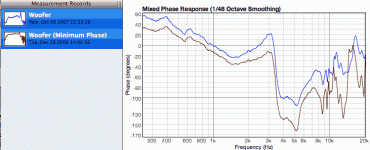
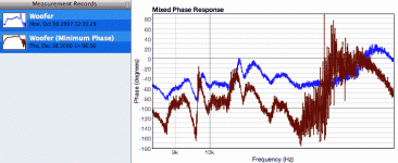
I've just produced a figure, showing the differences between measured phase, and calculated mimum phase from the frequency response of a C2 220 woofer. As one can see from the figures, above breakup the figures shows a difference between measured and minimum phase response. Hence, above breakup, the speaker doesn't act as a minimum phase system, and hence must be non-linear.
Marc
Marc
Attachments
Nonsense
Sorry to be blunt here, but that is nonsense. I've been measuring and modeling raw drivers for over 10 years and have never had any driver not be minimum-phase up to 20KHz +, including large, 10" drivers. Many others with more experience that I concur. That argument for non-linearity is flat wrong. Either your measurements are wrong or your model is inaccurate.
Dave
marche said:I've just produced a figure, showing the differences between measured phase, and calculated mimum phase from the frequency response of a C2 220 woofer. As one can see from the figures, above breakup the figures shows a difference between measured and minimum phase response. Hence, above breakup, the speaker doesn't act as a minimum phase system, and hence must be non-linear.
Marc
Sorry to be blunt here, but that is nonsense. I've been measuring and modeling raw drivers for over 10 years and have never had any driver not be minimum-phase up to 20KHz +, including large, 10" drivers. Many others with more experience that I concur. That argument for non-linearity is flat wrong. Either your measurements are wrong or your model is inaccurate.
Dave
- Status
- This old topic is closed. If you want to reopen this topic, contact a moderator using the "Report Post" button.
- Home
- Loudspeakers
- Multi-Way
- Accuton underhung neodym drivers