I can not get good agreement between my box simulations and my measurements of built boxes, what is your experiencies and what softwares works good for you?

How/where did you measure?
I think simulation accuracy mostly depends on correctness of data provided to simulation software.
Can you give an example? Whats different?
I think simulation accuracy mostly depends on correctness of data provided to simulation software.
Can you give an example? Whats different?
A biggie that sometimes happens is if you use manufacturer supplied parameters rather than Theile/Small parameters you actually measured yourself on the drivers that you actually get. The data from a number of woofer makers can be "not-even-similar" to as-measured values, a few are rather notorious about that.
Also it might depend on how you are measuring. Unless you can measure near-field, room effects will dominate (usually quite a bit more than the box performance will!) and near-field measurement of ported speakers involves some non-obvious technique.
Also it might depend on how you are measuring. Unless you can measure near-field, room effects will dominate (usually quite a bit more than the box performance will!) and near-field measurement of ported speakers involves some non-obvious technique.
first i measure the woofer free air t/s parameters
then i enter the numbers in the simulation software
i simulate a known sealed box for the woofer
then i measure the woofer in the sealed box
result: they do not match up, i just can not get the box q and box resonance to match the measured response
something must alter the driver parameters when put in the box, or maybe the simulation or the measurement gives bad data?
Last edited:
What exactly do you measure? Electrical impedance vs. frequency? Acoustic output? Can you show an example of your input parameters, box dimensions, and measured data?
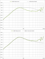
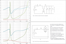
I'm not sure if this is related to your problem, but if the woofer you are using has significant inductance at lower frequencies, you won’t get good matches with most simulation software. This is often the case with modern subwoofers. Attached is an example comparing measurement and simulation for the Dayton 12” classic subwoofer. You can see that the new semi-inductance model provides near perfect match with measured response as well as measured impedance. The traditional model falls short.I can not get good agreement between my box simulations and my measurements of built boxes, what is your experiencies and what softwares works good for you?
Currently, Hornresp is probably your best choice for modeling software that incorporates this.
For more information on the semi-inductance model see thread here:
Semi-Le_Calc: Calculator for Advanced Inductance Model Incorporating Semi-Inductance
Attachments
Correct me if I'm wrong, but I do not understand all this suffering around the box tuning, which in my opinion, is the simplest of all the complicated tasks in the design process. To all use and practical effect, the minimum of excursion recorded by the microphone few millimeters ahead the woofer cap, IS the effective tuning freq.
Hi Mosquito (funny handle)
I think that there are two different issues here. One is the establishment of the actual Fb and the other is the modeling ability to design the box to begin with. In order to design the box, you would need a simulation program that you can count on to help you get near expected results once the enclosure is built. bolserst is helping with this and mentions software that may be more dependable.
Jay
Currently, Hornresp is probably your best choice for modeling software that incorporates this.
Do you know any other simulators which are using extended impedance model with Leb, Le, Ke and Rss? If yes, why they are worse than hornresp?
Yes, there are 2 others that I am aware of as mentioned at the link in Post #6
Modeling software that supports the Semi-Inductance model:
- Hornresp
- VituixCad
- SoundEasy
I few more details from the VituixCad and SoundEasy Manuals posted here:
Semi-Le_Calc Post#13
I recommended Hornresp because it is only a box modeling program, so likely easier to get going with than the fuller featured simulation tools of VituixCad and SoundEasy. If you know of any other simulation tools that offer this capability, please let me know and I will add them to the list.
so likely easier to get going with
I really don't buy this, though it's not big secret that I'm the author of VituixCAD.
Something to read why simulators might be different: About the ports and differences between various equations and design software calculations by J.Ahonen
I guess majority of simulators calculate for example Fb of vented box:
Cab=Vb/ro/c/c
Map=ro/Sp/n*(Lv+K*Dv)
Fb=1/2/pi/sqrt(Cab*Map)
User enters Vb, n, Dv, Lv and end correction K which is probably the main source for error along with different losses (Rab, Ral). Especially end correction K varies depending on shape and location of the port(s). Calculated Fb is typically higher than actual which leads to suspect that common default value K=0.732 is too small also for ports with single free end. Therefore default value in VituixCAD is 0.8. User is finally responsible to study and give parameters which are suitable for box and vent construction.
Lossy inductance has also some effect but that is quite easy to eliminate by measuring free air impedance response and extracting Leb, Le, Ke and Rss with suitable software, if not given by manufacturer.
Last edited:
I agree Kimmo. Classic models do not really account for flare of the port well (with different degrees of flare impacting the tuning a little differently). The proximity effect (how closely the port is placed to a boundary or the number of boundaries close to the port) are also not well accounted for. I seem to remember Salvatti, Button, and DeVantier may have written something about it with some fine tuning formulae.
I use 'basta'! and it has a 'le loss' feature which i use when simulate, i change the 'le value' and the 'le loss value' to track an actual free air impedance measurement curve of the woofer used. Then, when i simulate this woofer in a test cab (sonotube) i just can not get simulation to match actual impedance measurements for the woofer in the test cab regarding box q and box resonance.
^Could you give internal dimensions of sonotube, tell something about filling and attach or upload impedance measurements in free air and boxed?
The magnitude of the impedance peak will not match unless you are using a very stiff enclosure and no damping material. Wood and cardboard enclosures are flexible enough to reduce the magnitude of the peak a significant amount. An added complication is that the suspension damping is assumed to be constant when in reality it trends slightly with frequency. The magnitude of the peak is a measure of the mechanical Q of the driver/enclosure system. Fortunately, when driven by a voltage source the SPL response is dictated by the total Q of the system which is generally dominated by the electrical Q. In short if it is the impedance magnitude you are having problems matching up, that is to be expected and not an operational concern.…just can not get simulation to match actual impedance measurements for the woofer in the test cab regarding box q and box resonance.
The frequency of the impedance peak should match very well if you determined correct values for driver compliance (Vas), the enclosure volume(Vb), and aren’t using any damping material. Damping material can effectively increase the acoustic size of the enclosure. If you aren't using any damping and the frequency doesn’t match, either Vb or Vas is in error.
I agree with kimmosto, if you can provide your measured impedance data and enclosure dimensions it would greatly aid in resolving the discrepancy you are seeing. It would also be helpful to include the impedance data and details of how you determined the TSP of the woofer you are using for modeling.
BTW, if interested in seeing impedance measurements showing damping trends in an extremely stiff aluminum enclosure, see presentation here:
"Losses in Loudspeaker Enclosures," MOC Presentation 2011, Claus Futtrup
http://www.cfuttrup.com/about/15-Scan_Speak.pdf
http://www.cfuttrup.com/about/scan_speak.mp3 (audio of presentation)
I also found Hornresp to be accurate. It showed the internal reflections/resonances that matched my measurements.
- Status
- Not open for further replies.
- Home
- Design & Build
- Software Tools
- Accurate box simulations