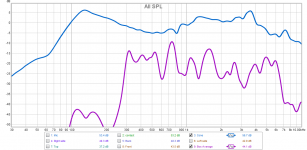
Here is what I found this morning. Below you will see two charts, they are the same measurements, the first with 1/12 octave smoothing, the second with 1/2 octave smoothing. The smoother one makes it easier to see trends.
These are the levels coming from the cone vs coming from the box. The cone plot is an average of 5 measurements at different places on the cone, mic distance 6mm from the cone. The box measurement is an average of left and right sides, top and front with the contact mic. The contact mic has been calibrated/normalized against the measurement mic so that it is closely equal to the measurement mic in both FR and sensitivity - closer than 0.2dB from 20-10,000 Hz.
The box noise per face is approximately 15-20 dB lower than the cone SPL. However - the cone has and SD of 133 cm2 and the box an SD of 2471 cm2. So I don't really know how the true SPL coming off the box. Interesting that the 12mm MDF does well under 300 Hz, but not great above that. Doesn't make sense to me.
Attachments

If possible, could you post a picture of your measurement setup?
I think a 12" distance(100db for the initial driver on axis) for all mic measurements is probably all you need. 6mm is probably much too close to get the gestalt of what's happening.
I also think that the contact mic will give some very limited information for corroborating with what the mic is picking up, but that's probably about it.
Last edited:
Yes I can take some photos. The reason I used 6mm and averaged the measurements over 5 spots was to isolate cone sound from box sound. That close to the cone means that the cone should dominate over any extraneous sounds or box noise. At 12" from the cone, how much of the box noise would be picked up?
With the contact mic there is a little bit of pickup thru the air, but it's so far below the contact vibrations that it shouldn't matter.
With the contact mic there is a little bit of pickup thru the air, but it's so far below the contact vibrations that it shouldn't matter.
Ah, got it. You did say that the box was cheap, quick, single driver job from a while back, so box noise relative to the direct driver output will definitely be more of a concern. That's a tough one to get right.
What 6" full range driver are you using?Yes I can take some photos. The reason I used 6mm and averaged the measurements over 5 spots was to isolate cone sound from box sound. That close to the cone means that the cone should dominate over any extraneous sounds or box noise. At 12" from the cone, how much of the box noise would be picked up?
With the contact mic there is a little bit of pickup thru the air, but it's so far below the contact vibrations that it shouldn't matter.
I think it's either a GRS or Goldwood. Don't remember which. Boxes are 13"Hx9.5"Wx7.5" deep. Sealed.
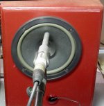
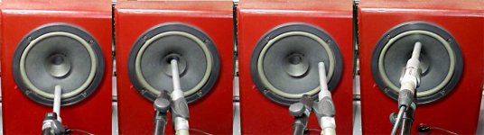
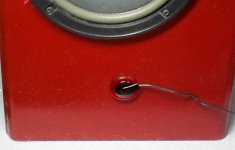
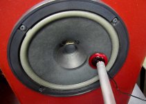
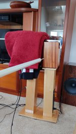
Here is the setup. Cone was an average measurement at: center 12:00, 3:00, 6:00, 9:00 (not shown). Contact mic on the cone for calibration was done as below, plus 12:00, 8:00, 9:00 around the sensor. Contact mic also shown on the baffle.
Here is the setup. Cone was an average measurement at: center 12:00, 3:00, 6:00, 9:00 (not shown). Contact mic on the cone for calibration was done as below, plus 12:00, 8:00, 9:00 around the sensor. Contact mic also shown on the baffle.
Attachments
Thanks!
I'm lucky to still have the Dunlavy's, with my side panel mic measurements corroborating(To a certain degree) with John Atkinsons accelerometer side panel measurements and used as a control against my own speakers. You don't get opportunities like that very often. It added some extra validity to the measurements. I still can't believe they didn't put any kind of brace in it. All the larger speakers the company made used the "box within a box" technique. Several boxes within a box, actually. I think they probably just pulled this box from the SC-6 design without making any modifications.
This was their largest. It used internally the same SC-1 speakers that I have, with a high pass filter on the mid-basses
Dunlavy Audio Labs Signature SC-VI loudspeaker | Stereophile.com
Last edited:
You're welcome. I'm happy to know (more or less) the the FR and level of the contact mic. That should make panel measurements useful.
With my small MDF boxes, it seems that the midrange is what's making the panels sing. I would have expected it to be the bass, but maybe the panels are too small for frequencies under 300 Hz to get them moving. Still not sure about that one.
With my small MDF boxes, it seems that the midrange is what's making the panels sing. I would have expected it to be the bass, but maybe the panels are too small for frequencies under 300 Hz to get them moving. Still not sure about that one.
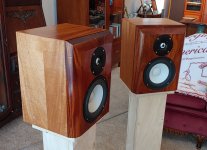
I employed the Remlab technique on my satellite speakers. Only the 6 inch drivers were active, tweeter and big woofer were muted. Normally there would be a crossover filter at 200 and 2000 Hz, but in this case the 6 inch driver was run full range.
First of all, I was amazed at the level of cancellation with mono pink noise. Just as Remlab has stated, this is an easy technique to isolate cabinet radiation from driver radiation. How is it that no one ever thought to do this before? John Atkinson did it once, but then never again? No one until Remlab ? wow.
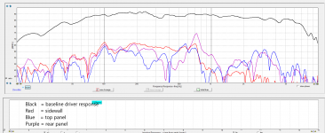
The baseline measurements were taken at 13 inches, on axis with the 6 inch mid driver. The various cabinet measurements were taken at a distance of 13 inches, centered on the panel. I used both a swept sinewave and psuedo noise sequence to make the measurements and found there was no difference (there is rarely any difference below 2 kHz).
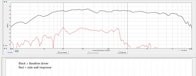
I made 3 measurements of the cabinets: sidewall, top panel, and rear panel.
I am getting a consistent 25 dB attenuation from 30 Hz to 1 kHz, except a rear panel peak at 730 Hz which rised to -15 dB.
When playing a sustained 730 Hz sinewave signal, I could detect the increase in volume, but it did not sound "resonancy". Once my ear was accustomed to the 730 Hz tone, I listened with program material to see if it was revealed. Thankfully it was not. I ran both speakers with a mono signal. I listened to female voice (Tuck and Patti, Adele, Lady Gaga, and Delibes Lakmé - The flower duet), massed violin (Beethoven 6th pastoral), hard rock (red hot chili peppers, stadium arcadium). It was weird listening to almost fully nulled-out music, but I never heard what could be caracterized as stored energy or "ringing" at 730 Hz.
So overall I am pleased with these cabinets.
First of all, I was amazed at the level of cancellation with mono pink noise. Just as Remlab has stated, this is an easy technique to isolate cabinet radiation from driver radiation. How is it that no one ever thought to do this before? John Atkinson did it once, but then never again? No one until Remlab ? wow.
The baseline measurements were taken at 13 inches, on axis with the 6 inch mid driver. The various cabinet measurements were taken at a distance of 13 inches, centered on the panel. I used both a swept sinewave and psuedo noise sequence to make the measurements and found there was no difference (there is rarely any difference below 2 kHz).
I made 3 measurements of the cabinets: sidewall, top panel, and rear panel.
I am getting a consistent 25 dB attenuation from 30 Hz to 1 kHz, except a rear panel peak at 730 Hz which rised to -15 dB.
When playing a sustained 730 Hz sinewave signal, I could detect the increase in volume, but it did not sound "resonancy". Once my ear was accustomed to the 730 Hz tone, I listened with program material to see if it was revealed. Thankfully it was not. I ran both speakers with a mono signal. I listened to female voice (Tuck and Patti, Adele, Lady Gaga, and Delibes Lakmé - The flower duet), massed violin (Beethoven 6th pastoral), hard rock (red hot chili peppers, stadium arcadium). It was weird listening to almost fully nulled-out music, but I never heard what could be caracterized as stored energy or "ringing" at 730 Hz.
So overall I am pleased with these cabinets.
Attachments

Your baseline driver plot was taken with the speaker as per normal usage?
It has long been used to cancel noise when doing woofer break-in. I learned it in the 1980s. But I haven't seen it used for cabinet measurements like this.First of all, I was amazed at the level of cancellation with mono pink noise. Just as Remlab has stated, this is an easy technique to isolate cabinet radiation from driver radiation. How is it that no one ever thought to do this before? John Atkinson did it once, but then never again? No one until Remlab ?
With the front exposed..
Dunlavy Audio SC VI Speakers - Monstrous Sound at 91db Efficiency! – SkyFi Audio
Dunlavy Audio SC VI Speakers - Monstrous Sound at 91db Efficiency! – SkyFi Audio
I employed the Remlab technique on my satellite speakers. Only the 6 inch drivers were active, tweeter and big woofer were muted. Normally there would be a crossover filter at 200 and 2000 Hz, but in this case the 6 inch driver was run full range.
First of all, I was amazed at the level of cancellation with mono pink noise. Just as Remlab has stated, this is an easy technique to isolate cabinet radiation from driver radiation. How is it that no one ever thought to do this before? John Atkinson did it once, but then never again? No one until Remlab ? wow.
The baseline measurements were taken at 13 inches, on axis with the 6 inch mid driver. The various cabinet measurements were taken at a distance of 13 inches, centered on the panel. I used both a swept sinewave and psuedo noise sequence to make the measurements and found there was no difference (there is rarely any difference below 2 kHz).
I made 3 measurements of the cabinets: sidewall, top panel, and rear panel.
I am getting a consistent 25 dB attenuation from 30 Hz to 1 kHz, except a rear panel peak at 730 Hz which rised to -15 dB.
When playing a sustained 730 Hz sinewave signal, I could detect the increase in volume, but it did not sound "resonancy". Once my ear was accustomed to the 730 Hz tone, I listened with program material to see if it was revealed. Thankfully it was not. I ran both speakers with a mono signal. I listened to female voice (Tuck and Patti, Adele, Lady Gaga, and Delibes Lakmé - The flower duet), massed violin (Beethoven 6th pastoral), hard rock (red hot chili peppers, stadium arcadium). It was weird listening to almost fully nulled-out music, but I never heard what could be caracterized as stored energy or "ringing" at 730 Hz.
So overall I am pleased with these cabinets.
I couldn't believe that back in '94, JA didn't see the potential value in his own observation. Or maybe it was simply that he didn't want to hassle with another measurement that's fairly easy to perform on bookshelf speakers, but would be terrible to perform on big, heavy, expensive monsters.
Outstanding measurement set, by the way!
Last edited:
hifijim,
https://www.diyaudio.com/forums/att...ometers-measure-panel-vibrations-sidewall-png
That's very impressive and controlled extension on both ends for a wide open 6" driver. What is it?
https://www.diyaudio.com/forums/att...ometers-measure-panel-vibrations-sidewall-png
That's very impressive and controlled extension on both ends for a wide open 6" driver. What is it?
Last edited:
Your baseline driver plot was taken with the speaker as per normal usage?
Yes, I made the baseline FR measurement on-axis, so the device under test (the right hand speaker) was turned 90 degrees and facing the mic.
That's very impressive and controlled extension on both ends for a wide open 6" driver. What is it?
It is an SB17CAC35-4. Although I disabled the 200 and 2k crossover filters, I left all the other driver EQ in place. This is why it looks so smooth and extended. I use DSP to implement IIR filtering and EQ by way of the Hypex fusion amp.
I have an 8 db first order shelf at 390 Hz (BSC), a -2 dB Q=3.0 cut at 1.3 kHz, a +5 dB Q=2.5 boost at 4.9 kHz, and a -9 dB Q=3.0 cut at 9 kHz. So there is a lot going on to make it flat.
I have to admit, when you first floated the idea of running two speakers out of phase but facing each other in the hopes of capturing cabinet response, I was skeptical... my thought was "if it were that easy, everyone would be doing it"... Pretty cool.
Attachments
Jeah it is very exciting, second big thumb for 2020 in DIY audio! My first thumb went to the mabat acoustic horn design work. At least some positives for the weird year🙂
edit. hah, mabat work started 2019. Tine flies... Anyway, great work remlab! 🙂
edit. hah, mabat work started 2019. Tine flies... Anyway, great work remlab! 🙂
Last edited:
I have to admit, when you first floated the idea of running two speakers out of phase but facing each other in the hopes of capturing cabinet response, I was skeptical... my thought was "if it were that easy, everyone would be doing it"...
Indeed. At the risk of dampening enthusiasm can I suggest a bit of basic checking?
The expected behaviour for an arrangement like this is:
- large cancellation of fundamental
- enhancement and reduction of harmonics
- degradation due to differing driver parameters
- sound from the baffle
- some form of cavity resonance
So measure to see to what degree this is occurring. Perform a typical measurement including harmonics. Place the microphone close to the gap and check that you are measuring mostly enhanced and reduced harmonics as expected.
If you are getting good cancellation then place something like a door sealing strip, stiff foam, rubber,... around the outside of the baffle in order to seal the gap with minimal influence on the cabinet motion.
The two cabinets will be creating a more complex and quieter radiation pattern than a single cabinet and, more importantly, the radiation from the baffle will be missing. This is normally the most important because it is hammered on by the heavy drivers, weakened by holes being cut out and radiates sound directly at the listener.
So place a microphone close to a panel (or contact microphone on panel) and check you are measuring as expected a typical cabinet response (see BBC, KEF and others for examples). That is, a few high Q resonances. Do not average the frequency bins because it destroys this information. Use a fine resolution in frequency and ensemble average if possible.
If you are getting what is expected then move towards the far field and check you are still seeing cabinet radiation. That is, high Q resonances and possibly cancellation dips.
I do not want to spoil the party, but has anyone here calculated the SPL that results when the two speakers differ just 0,5dB SPL from each other?
This isn't a big problem with contact mics or accelerometers as they primarily pick up vibration thru contact, not the air.
With the two facing speakers I could not get a good acoustic null above the bass region. Cheap, likely mismatched, drivers doesn't help achieve the null.
I'm about to try moving the two face to face speakers around while listening for the best null. Will report back soon.
With the two facing speakers I could not get a good acoustic null above the bass region. Cheap, likely mismatched, drivers doesn't help achieve the null.
I'm about to try moving the two face to face speakers around while listening for the best null. Will report back soon.
I used the contact mic as a stethoscope and listened to pink noise at various points around the surface of the box. It was fun to do and results were about what you'd expect. The center of the panels is the loudest, the corners the quietest. Between top and bottom there is a noticeable difference, so that's useful info.
Putting two speakers face to face while playing pink noise in opposite polarity is also informative. Getting the drivers too far apart (only a few cm) quickly kills the HF null. Rotating one speaker slightly so that the two speakers are no longer exactly aligned also wipes out the HF null. The deepest audible null I found was face to face with the frames touching.
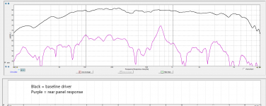
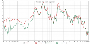
While listening thru the contact mic, I played one speaker and then included the opposite speaker to make the null. With the two speaker null, there was a drop in bass thru the contact mic, as tho the bass was being cancelled by the opposite speaker. In fact it was, below is a graph that shows vibration on the rear panel with one speaker playing and with two speakers playing in phase cancellation. As you can see, the cancellation mostly effects the low end in this particular setup.
Putting two speakers face to face while playing pink noise in opposite polarity is also informative. Getting the drivers too far apart (only a few cm) quickly kills the HF null. Rotating one speaker slightly so that the two speakers are no longer exactly aligned also wipes out the HF null. The deepest audible null I found was face to face with the frames touching.
While listening thru the contact mic, I played one speaker and then included the opposite speaker to make the null. With the two speaker null, there was a drop in bass thru the contact mic, as tho the bass was being cancelled by the opposite speaker. In fact it was, below is a graph that shows vibration on the rear panel with one speaker playing and with two speakers playing in phase cancellation. As you can see, the cancellation mostly effects the low end in this particular setup.
Attachments
I do not want to spoil the party, but has anyone here calculated the SPL that results when the two speakers differ just 0,5dB SPL from each other?
If we assume we could get a perfect cancellation null with perfectly matched drivers, then a 0.5 dB driver difference would equate to a signal that is -24.8 dB below the baseline. A 1 dB driver mismatch would equate to a -18.8 dB signal.
So there is definitely a limit to the resolution. For my purposes, a resolution that is 20 to 25 dB below the baseline driver radiation is good enough.
- Home
- Loudspeakers
- Multi-Way
- Accelerometers to measure panel vibrations?