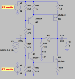
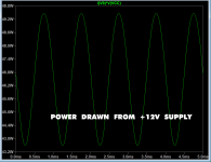
Schematic from post # 3,113 draws a surprising amount of power from the puny +/- 12 volt supply rails. It can drive an 8 ohm speaker to ~ 9 watts and remain in Class A the whole time.
Play with the numbers: 47 watts from the +12 supply, and another 47 watts from the -12 supply, gives you 9 watts into the speaker. Surprising!
_
Play with the numbers: 47 watts from the +12 supply, and another 47 watts from the -12 supply, gives you 9 watts into the speaker. Surprising!
_
Attachments

sorting biasing is trivial per se, same as establishing proper Rin (shown as is is ridiculously low), but main thing is stability of all factors in temperature domain
anyhow, if speaking only about building an amp, it's nonsense trying to save 50$ when building an amp worth at least 40 times more
but, if name of the game is learning and trying something new, that's another (shiny) kettle
anyhow, if speaking only about building an amp, it's nonsense trying to save 50$ when building an amp worth at least 40 times more
but, if name of the game is learning and trying something new, that's another (shiny) kettle
I got some promising "gibberish", mosfets behave almost like jfets but they need bias voltage which is doable, also i need to get it back to single supply and find better mosfet models, preferably some low power mosfet models.sorting biasing is trivial per se, same as establishing proper Rin (shown as is is ridiculously low), but main thing is stability of all factors in temperature domain
anyhow, if speaking only about building an amp, it's nonsense trying to save 50$ when building an amp worth at least 40 times more
but, if name of the game is learning and trying something new, that's another (shiny) kettle
Hi im trying to built an ACA mini but without the input jfets becuse of an severe case of: "Expensive International Shipping" i cant get them locally, i also believe its a good project and learning exercise.
Im currently on this "promising" schematic:

That seems to just need biasing.
Im currently on this "promising" schematic:
That seems to just need biasing.
Have a fun time and good luck on your project!
ok i found an j176/j113 jfet pair for cheap locally and after simulating the amplifier i get ~50w of power dissipation per transistor, is there any specific reason for the irf520/irf9520 pair or did i do something wrong?

R26 and R30 need to be variable with the FET gate taken from the wiper.
It is a neat project 🙂
Here is a sim for anyone interested. It is not meant to be definitive and uses only standard LTspice models (so its click and run) but you can explore the operating conditions and so on.
The first FFT is with the bypass cap and series 1 ohm across the 0.75 ohm. The second FFT is with those removed. The standing current is set to 400ma. The FFT's were done with all caps set to '1' (one Farad). The load impedance is set at 6 ohm.
Oh thanks the wiper was connected in a weird way on the schematic.
How much does the exact transistor model matter? Will something like the irf540/9540 work just as well?
How much does the exact transistor model matter? Will something like the irf540/9540 work just as well?
Last edited:
The exact model makes little difference if you bias it correctly. Remember the resistor values you set for biasing will be different from the values needed in a real build.

What is your conclusion @MoolyR26 and R30 need to be variable with the FET gate taken from the wiper.
It is a neat project 🙂
Here is a sim for anyone interested. It is not meant to be definitive and uses only standard LTspice models (so its click and run) but you can explore the operating conditions and so on.
The first FFT is with the bypass cap and series 1 ohm across the 0.75 ohm. The second FFT is with those removed. The standing current is set to 400ma. The FFT's were done with all caps set to '1' (one Farad). The load impedance is set at 6 ohm.
Should we bypass?
You should design your PCB to include a jumper, which lets you select between bypass and not-bypass. In exactly the same way that Nelson Pass's layout of the ACA Mini PCB includes a jumper. Then you can listen to your version of the ACA mini both ways, and decide which one pleases you the most.Should we bypass?
Bypass what? If you mean the 0.75 ohm with a cap then I have no idea 😉 I've never built any of these let alone listened to them.Should we bypass?
- Home
- Amplifiers
- Solid State
- ACA mini mosFET/BJT input, thread spun off from here: [https://www.diyaudio.com/community/threads/diy-aca-mini.379037/post-7946869]