Hi all!
Just finished building this amp and have issues with one channel not working. Once turned on, it just "farts" on the speaker, sounds like a 3 second discgarge noise for the lack of better explanation.
I've removed that channel out of the chassis and tested again isolated, same issue. All components check out measure vise (resistors and caps). Placement is exact as on the working channel. Did the resistance messurements suggested by the manual and here are the results (output connected, input and PSU disconnected):
Q1 -- S = 0, D = 4.96 k, G = 1 k
Q2 -- S=4.96 k, D = 1 k, G = 11.1 k
Q3 -- B = 5.65 k, C = 10.9 k, E = 4.96 k
Q4 -- S = 990, D = 1 k, G = 334 k
Is there any doc that shows how to test for correct voltages? Any help is greatly appreciated!
Thanks!!
There are good troubleshooting diagrams and photos in the build guide. They are at the end. Voltage check has helped me any time a channel was not working.
Please post some well lit and close-up pictures of your boards and wiring.
See the build guide, post #56 "Troubleshooting". Pictures 2-3 in that step have voltages.
https://guides.diyaudio.com/Guide/Amp+Camp+Amp+V1.6+Build+Guide/5
See the build guide, post #56 "Troubleshooting". Pictures 2-3 in that step have voltages.
https://guides.diyaudio.com/Guide/Amp+Camp+Amp+V1.6+Build+Guide/5

Measure dc resistance across your RCA input connector. (Center conductor to chassis). Sounds like it is shorted.
Thanks everyone for jumping on this! Somehow I've missed the voltage pic. Here it is:
Q1 -- S = 0.04 V, D = 12.08 V, G = 4.6 V
Q2 -- S = 12.9 V, D = 23.86 V, G = 17.5 V
Q3 -- C = 17.62 V, B = 12.7 V, E = 12.11 V
Q4 -- S = 4.63 V, D = 23.87 V, G = 4.42 V
Everything looks in spec...this is strange...
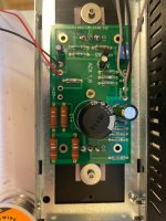
Picture attached. Curently only power input is connected. When testing, IN + and - goes to input signal cable + and -, OUT + goes to + lead on speaker and ground, - goes to negative lead on speaker.
Hope this helps!! Thanks!
Q1 -- S = 0.04 V, D = 12.08 V, G = 4.6 V
Q2 -- S = 12.9 V, D = 23.86 V, G = 17.5 V
Q3 -- C = 17.62 V, B = 12.7 V, E = 12.11 V
Q4 -- S = 4.63 V, D = 23.87 V, G = 4.42 V
Everything looks in spec...this is strange...
Picture attached. Curently only power input is connected. When testing, IN + and - goes to input signal cable + and -, OUT + goes to + lead on speaker and ground, - goes to negative lead on speaker.
Hope this helps!! Thanks!
Attachments
Output positive (speaker positive) is actually ground. Output negative is not connected to ground. Inverting amp design
Correct. Positive output lead connects to positive speaker port and power input ground and negative output lead connects to negative speaker port.Just checking, the positive output lead also connects to the power input ground?
But the negative output is.
Update: biggest cap negative lead also shorts to gnd and there is no visual mechanical bridges. Bad cap?
Update: biggest cap negative lead also shorts to gnd and there is no visual mechanical bridges. Bad cap?
Last edited:
@tjw59 there is no input connected.
To summarize:
What am I missing? Should I ask for a refund or new transistors for the board?
Thanks
To summarize:
- board is out of the chassis
- all caps and resistors have been checked individually
- no shorts on signal input or output
- resistance check, input disconnected, output connected:
- Q1 -- S = 0, D = 4.96 k, G = 1 k
- Q2 -- S = 4.96 k, D = 1 k, G = 11.1 k
- Q3 -- B = 5.65 k, C = 10.9 k, E = 4.96 k
- Q4 -- S = 990, D = 1 k, G = 334 k
- voltage check, power in connected, signal in and out disconnected:
- Q1 -- S = 0.04 V, D = 12.08 V, G = 4.6 V
- Q2 -- S = 12.9 V, D = 23.86 V, G = 17.5 V
- Q3 -- C = 17.62 V, B = 12.7 V, E = 12.11 V
- Q4 -- S = 4.63 V, D = 23.87 V, G = 4.42 V
What am I missing? Should I ask for a refund or new transistors for the board?
Thanks
Your voltages and resistances look reasonable so I do not think there are any problems with the transistors.
Check your solder joints at C1 and R14. If uncertain, reflow them.
Also with no speaker connected, set you meter to DCV and connect it to speaker out, and turn on the power. Is there constant DC voltage, or does the DC voltage appear and quickly go to zero?
Check your solder joints at C1 and R14. If uncertain, reflow them.
Also with no speaker connected, set you meter to DCV and connect it to speaker out, and turn on the power. Is there constant DC voltage, or does the DC voltage appear and quickly go to zero?
Joints test ok but I did reflow them. Speaker out shows climb to around 5 V and then drop to 0 within 10 seconds. Then it starts to climb again...
When it started to climb, how high did it go and did it then stay constant?
Also short the input+ to ground and repeat the test.
Also short the input+ to ground and repeat the test.
It goes up to 5.7 V. That climb lasts 5 seconds.
Then it drops down to 0 V. That drop lasts another 5 seconds. So no, it does not stay constant.
With input shorted, output stays 0 V.
Then it drops down to 0 V. That drop lasts another 5 seconds. So no, it does not stay constant.
With input shorted, output stays 0 V.

- Home
- Amplifiers
- Pass Labs
- ACA - help needed