There is another simple formula to find that current from the voltage across the trimmer resistor. You already know what the Drain voltage of Q1 is, about 12.5V. Same voltage as the trimmer. (The current entering the trim pot at the wiper is insignificant.)
31.25 mw12.5 x 12.5= 156.25 / 5000= .03125 or 31.25 watts should be okay

Tungsten you have been kind of a hero of mine reading the Premium aca thread and the amount of work you have given to it and now you have taken the time to teach me to………fish !!! Thank you mark
I wholeheartedly second this!!!Tungsten you have been kind of a hero of mine reading the Premium aca thread and the amount of work you have given to it and now you have taken the time to teach me to………fish !!! Thank you mark
Tungsten I need some more help. I got these boards from Rudi and haven’t been able to get a hold of him. Since I could only get a 20volt secondary transformer He put in two series diodes on the output of the cap multiplier if I needed to drop the voltage. I installed both and have about 22.6 volts. each diode drops 1.1 volts so if I delete one of them theoretically I will have close to 24 volts. My question is can I short across the last diode without hurting it and see if the voltage increases what I think it will? Boards are built and everything works just less than 24volts thanks mark
Attachments
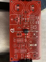
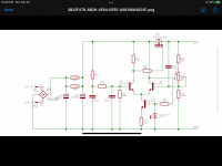
Using diodes to reduce the voltage of a cap multiplier is an unusual technique. Not what I would recommend. Do you have the schematic for this board?
While it is possible to try shorting across one or both diodes (the ACA will run happily on a little higher supply voltage), it would be better to make sure we understand how the board is working first.
While it is possible to try shorting across one or both diodes (the ACA will run happily on a little higher supply voltage), it would be better to make sure we understand how the board is working first.
How high a voltage would the amp be happy with, 26v to 27v okay? I have a schematic for cap multiplier without the diodes and the aca is your version. will send later, thank you tungsten
Yes, 26V to 27V is fine. Especially if the amp portion includes a 200 Ohm R16 above the drain of the input JFet. That is part of my ACA modifications.
@bubba177, I have the same boards from Rudy and I think your don't need any diodes. With 20V transformer, you will get 28V. You reduce around 1V for drop across diode which makes it 27 V. The additional 3V are to be dropped across the pass transistor in capacitance multiplier section. This you do with the pot in this section. So, my guess is, 20V is not an issue....Tungsten I need some more help. I got these boards from Rudi and haven’t been able to get a hold of him. Since I could only get a 20volt secondary transformer He put in two series diodes on the output of the cap multiplier if I needed to drop the voltage. I installed both and have about 22.6 volts. each diode drops 1.1 volts so if I delete one of them theoretically I will have close to 24 volts. My question is can I short across the last diode without hurting it and see if the voltage increases what I think it will? Boards are built and everything works just less than 24volts thanks mark
You can build the cap multiplier section first and check the output voltage... Make sure you have a load that draws a current similar to the amplifier when adjusting cap multiplier.
Yes I took the diodes out got 24.5 volts that is puurrrfect . Does twiddling with the pots make much difference with your board?
How do you adjust the pots in cap section???Yes I took the diodes out got 24.5 volts that is puurrrfect . Does twiddling with the pots make much difference with your board?
If you are getting 24.5V without the diodes, then you are good to go. I would set VBias to 12.5V and run with that.
The pot in the cap multiplier circuit would be the usual way to set the supply voltage for the amplifier. I don’t know why those diodes were added. I consider that a mistake.
The pot in the cap multiplier circuit would be the usual way to set the supply voltage for the amplifier. I don’t know why those diodes were added. I consider that a mistake.
Hey bubba177,How do you adjust the pots in cap section???
I think that pot will adjust the drop out voltage across the pass transistor. But if you have used 50K multiturn pot, you may need to turn it quite a bit before you see its effect. But you will eventually be able to adjust the drop out voltage across pass transistor and hence the output voltage as well.
I have not yet built my board but I will do it in few weeks. I have built this same cap multiplier for other amps and know it works fine.
Thanks
Balaji
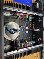
Baswamin I was surprised to learn dale 60 resistors didn’t fit this board. When you go to order parts don’t use your “my eye cromiter” like I did but a real one. Thanks for all your help gentleman will have this playing tomorrow
Attachments
I have a rack of IRFP150s that I bought to match when I built my Aleph J. I've been dying to use more of them in other designs, and then I discovered today that some people have been used them in the ACA. I imagine I can use '150s in my 4U chassis with the standard diyaudio store PSU, using a single +25V rail? I found Tungsten's modified circuit with the IRFP240s, so that seems like a good start for recalculating values of parts needed. I assume matching Q1 and Q2 is not required?
Yes, the IRFP150s will work well in the ACA. They are similar to using a pair of IRFP240s at each position and do not need to be matched. You can try single rail supplies from 25V to 36V.
See some of the previous posts on how this was done with the FQH44N10 devices. Very similar technique. A voltage dropping resistor "R16" above the drain of the input JFet is recommended for the higher voltages.
See some of the previous posts on how this was done with the FQH44N10 devices. Very similar technique. A voltage dropping resistor "R16" above the drain of the input JFet is recommended for the higher voltages.

- Home
- Amplifiers
- Pass Labs
- ACA amp with premium parts