Hi All.
Just a quick question about a headphone amp that I am working on. I am close to finishing an OTL 6AS7 amp from the archive of the Headwize site called "A Single-Ended OTL Amplifier for Dynamic Headphones by Aren van Ward". I have both the HT power supply and the heater supply in two enclosures separate from the main circuit, for a three enclosure circuit. I didn't use the same HT power supply as the posted schematic, but my implementation should provide less ripple to both power and pre tubes than the source schematic.
My question is whether I should use regular AC on the heaters sourced from a center tapped, 8 amp Hammond 6.3 volt transformer, or implement some sort of DC heater using this same transformer, which is already part of the build. I have not felt the need to use DC heaters before, but this is my first headphone amp, so I'm not sure if hum will be a problem if I don't.
The circuit as drawn uses a 9 volt transformer that is not center tapped. It was originally my intention to build the heater circuit by using a full wave rectifier, (taping off the center tap) and then going to 15000Uf or so of capacitance (I have room for triple that amount) placed between the positive and negative outputs of the rectifier, and then to the heaters. Is this a good plan? I have the room to implement any number of schemes, the only thing I am stuck with is the center tapped Hammond transformer. Should I not bother and use AC? Is DC elevation a better idea? Any suggestions and advice would be appreciated.
Last edited:
Try it with AC and if there's annoying hum then try DC unless you already have the parts (bridge, caps, dropping resistor or regulator) then go for it.
I've build the same circuit but I paralleled the output (added a second 6AS7, used 1k5 per pair of cathodes) to drive 16 ohm loads. I used a 12V transformer, a 25A bridge, 80000uf and a calculated dropping resistor to get 12V (I run the heaters in series, and used a 7806 with 22uf for the 6DJ8 heater) There is NO hum through the headphones using this setup. I only use AC on the heaters of push pull output tubes.
I've build the same circuit but I paralleled the output (added a second 6AS7, used 1k5 per pair of cathodes) to drive 16 ohm loads. I used a 12V transformer, a 25A bridge, 80000uf and a calculated dropping resistor to get 12V (I run the heaters in series, and used a 7806 with 22uf for the 6DJ8 heater) There is NO hum through the headphones using this setup. I only use AC on the heaters of push pull output tubes.
capacitance of heater winding against other power windings can transfer buzz, sometimes also through indirect heated cathodes.
therefore must ac-couple heaters to gnd, never let float
therefore must ac-couple heaters to gnd, never let float
The circuit as drawn does have DC heaters, as do most tube headphone amp circuits that I have come across. I would prefer not to use DC, as it complicates things and there seems to be some concern online with introducing hash through the SS rectifiers, and with DC making circuits quieter but adversely affecting the sound quality. Again, it's my first headphone amp, so all input is appreciated.
I've built that particular circuit a very long time ago. If you use AC, your power transformer will thank you. The 6AS7 wants 2.5A of heater current, and round it up to 3.25A for the driver tube. Now you also have to charge that cap input filter. You'll be wanting to look for at least a 5A winding to deal with that.
The circuit as-drawn has way, way too much gain. The 6DJ8 is overkill, and I'd recommend a 5687 instead. 10K looks like a great loadline with 150V available. I'd shoot for 2V of bias and 8mA. That's a 250 ohm cathode resistor (1/4W is ok) with a 10K plate load (2W or greater).
Dump C1 and R5, you don't need them.
R7 on the amplifier should be a lot smaller, no more than 2K in my opinion to keep the voltage spike damped when you turn the amp on.
Another option for dealing with excessive gain is to use a little feedback. You can make R2 10K, then add a 100K resistor in between the output of C3 and the grid side of R2. You can experiment with varying the value of the 100K resistor. As you go down, amplifier gain will decrease and output impedance will drop a bit (but you may not like the effect).
In the power supply, nodes are your friend! Don't be afraid to split the DCR of that choke into two smaller chokes. There are decent 470uF/250V caps, use those!
Last edited:
Or just build an Aikido style circuit 🙂 I did and no longer use this amp. (I've removed the "Aikido mojo since I'm running the heaters from a 12V switcher and the HV from a 12V to 280V boost converter and don't need the PSRR enhancement)
Attachments

Last edited:
audiowize:
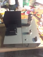
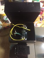
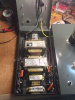
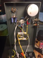
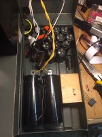
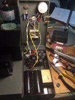
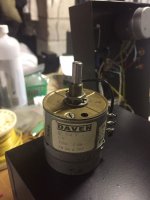
I am using the Hammond 167R6 which is rated at 6.3V at 8 amps, so I have the capacity to go either way. The black box on the top right on the amp will contain the components required to go DC on the heaters. There is plenty of room in there to add more capacitance (there is 3X 4700uF installed at the moment) as well as rectifiers resistors, etc. I have used two large 120v to 30v transformers with secondaries attached for the source of 120 volt AC. The power supply is CLCLC (117.5uF/1.5H/235uF/1.5H/235uF) to the power tube, then the rail is split to the right and left channel of the pre tubes with two sets of RCRC (2.2K/76uF/2.4K/2uF). The last C is a film cap, and all the rest of the C are made up a small portion of the bucket of 200 volt 470uF electrolytic capacitors I bought last summer, bypassed by small film caps. Thanks for the feedback idea, I'll try it out if I find there is too much gain. I will be using it with a pair of AKG K240 Sextetts, which are 600 Ohm, so the output capacitors are a pair of 100uF Obbligato film caps. I am also using one of the six Daven 2X100K stepped attenuators I picked up earlier this year as a volume control. Here are a few photos. It's a bit of a monster....
I am using the Hammond 167R6 which is rated at 6.3V at 8 amps, so I have the capacity to go either way. The black box on the top right on the amp will contain the components required to go DC on the heaters. There is plenty of room in there to add more capacitance (there is 3X 4700uF installed at the moment) as well as rectifiers resistors, etc. I have used two large 120v to 30v transformers with secondaries attached for the source of 120 volt AC. The power supply is CLCLC (117.5uF/1.5H/235uF/1.5H/235uF) to the power tube, then the rail is split to the right and left channel of the pre tubes with two sets of RCRC (2.2K/76uF/2.4K/2uF). The last C is a film cap, and all the rest of the C are made up a small portion of the bucket of 200 volt 470uF electrolytic capacitors I bought last summer, bypassed by small film caps. Thanks for the feedback idea, I'll try it out if I find there is too much gain. I will be using it with a pair of AKG K240 Sextetts, which are 600 Ohm, so the output capacitors are a pair of 100uF Obbligato film caps. I am also using one of the six Daven 2X100K stepped attenuators I picked up earlier this year as a volume control. Here are a few photos. It's a bit of a monster....
Attachments
Last edited:
kodabmx:
I think I'll try it with DC first, and up the capacitance as you did since I have the room to do so. I'm already set up for it as I was expecting to build the heater supply that is found in Mapletree Audio Design's OD300. This has a 6.3 volt transformer, a bridge rectifier, a 10000uF cap, one 47K resistor to ground off the negative and one off the positive after the capacitor, and then on to the tube heaters. I have heard this amp, and it is excellent.
I think I'll try it with DC first, and up the capacitance as you did since I have the room to do so. I'm already set up for it as I was expecting to build the heater supply that is found in Mapletree Audio Design's OD300. This has a 6.3 volt transformer, a bridge rectifier, a 10000uF cap, one 47K resistor to ground off the negative and one off the positive after the capacitor, and then on to the tube heaters. I have heard this amp, and it is excellent.
Or just build an Aikido style circuit 🙂 I did and no longer use this amp. (I've removed the "Aikido mojo since I'm running the heaters from a 12V switcher and the HV from a 12V to 280V boost converter and don't need the PSRR enhancement)
only the bottom 6n3p is affecting the tube sound.
Ideal follower has low Z out, and high gm, which triodes have some problems with that. (mosfet is better)
linear triode is great at voltage amplification, why to use it for anything else?
let the mosfet do the hard power work
only the bottom 6n3p is affecting the tube sound.
Ideal follower has low Z out, and high gm, which triodes have some problems with that. (mosfet is better)
linear triode is great at voltage amplification, why to use it for anything else?
let the mosfet do the hard power work
Because this is easier, cheaper, and works better.
I can build this circuit in a chassis with power supplies for less than 100 CAD. No bloody heatsinks either. It will drive 32 ohm headphones and it will deliver almost 1 Watt into my 470 ohm cans.
Every time I see an IC in a tube amp circuit, I get all sweaty and nervous. I've built a few with SS CCS, and the most annoying part for me is the heatsinking as well. They do sound pretty good, so I forced myself through it. Not this time though. I finished it using DC on the heaters (74000uF). It is dead quiet. I have only used it with the output of an Iphone, and that way the gain is not excessive. It will be a little too much with my DAC and my CD, but okay with my receivers DAC, which has an output similar in level to the Iphone. I needed to drop the heater voltage a bit, and did so with resistors. I ended up with a B+ of around 200V on the plates of the 6AS7/6080/5998, and 72V on the 6DJ8/6922/6n1p. The first is higher than my targeted 155-165v, and the second at 72V seems low. The transformers each have two secondary taps, and I used the combination that gave me 150V unloaded. I can also get 120V and 100V by a simple rewiring. if I lower it to 120V, as per the schematic, it will lower the B+ going to the pre tube as well, so I will have to lower the resistors in series to get it back up. What should I shoot for in voltage and current for both the 6080 and 6922? I have many 6n1p-ev as well. What would be good operating point for that tube?
Your operating point for the 6080 is limited by the dissipation of the cathode resistors. A 3.3K/10W resistor will dissipate 3.3 watts at about 33mA. I don't recommend pushing those resistors any hotter than that.
This is 108V of cathode voltage. I would shoot for 100V to keep some margin. What is your current 6080 cathode voltage?
If you need more voltage, you can raise the available voltage for the first stage, or decrease the value of the plate loading resistor. If you need less voltage, just increase the impedance of the plate load till you get what you want.
I have never found the need for DC heaters.
Any noise I have had has always been due to bad layout.
Just keep heater wires away from audio signals the best you can.
I always elevate heater volts to 45VDC decoupled.
Any noise I have had has always been due to bad layout.
Just keep heater wires away from audio signals the best you can.
I always elevate heater volts to 45VDC decoupled.
nigelwright7557:
I would agree with you as that has also been my experience with all the SET amps that I have built. However, because it was my first headphone amp, I wanted to make extra sure. The amp is so quiet that it is a great way to check tubes, both input and output, for issues, and I have found a few issues with some of the tubes I tested.
audiowize:
You must be psychic. I checked voltages earlier, and found that one of the cathode resistors had failed. I didn't have a 3.3K handy to replace it, so I put in a 1k ten watt plus a 2K ten watt to create a 3K. I also rewired to drop the voltage to 120V out of the transformers and 150.5V B+. The pre tubes have 62V at the plate resistor. Should I lower the plate resistors on the 6922 tube to bring that up to around 90V?
With these changes, I now have 88V across each 6AS7 cathode and 1.5 volts across each 6922 cathode. With a 5998 in the power tube position, I get 1.55 across the 6922 cathodes and 75V across the 5998 cathodes. With a 6N1P-EV in the pre position I get 1.33V across the cathodes, and 95V across the 6AS7 cathodes.
- Status
- Not open for further replies.
- Home
- Amplifiers
- Tubes / Valves
- AC or DC for OTL headphone amp heaters