I have a couple of older Garrard turntables that I have essentially taken apart and rebuilt over time.... I have completely disassembled the motors, cleaned, lubricated etc.......new motor mounts, roller, belts etc....still have a fine vibration that can be felt thru the tonearm......I have even put sorbothane mounts between the metal and the plinth. Taking into account the difference in line voltage from when these were made to now.....is there any merit in putting a resistor in series with the AC supply at the turntable to smooth out the motor?. If so, what value or type of resistor should I try.....Any other suggestions would be welcome..................thanks
Hi! I would be interested to know which Garrard turntables you have rebuilt. 🙂
You seem to have done all the right things to reduce the transfer of motor vibration to the turntable deck.
Does the 'fine' vibration that persists have an audible effect on the reproduction of your records?
I don't immediately see that putting a resistor in series with the motor supply will act to 'smooth out' the motor vibration.
For interest's sake, what is the difference in line voltage to which you refer?
O.K. I've found references to reducing the voltage to a Garrard synchronous motor, in order to reduce vibration, in this old diyAudio thread:
Cutting vibrations from a (Garrard) synchronous motor.
Cutting vibrations from a (Garrard) synchronous motor.
This would appear to be a suitable procedure to use with a shaded pole, AC synchronous, Garrard motor:
(a) Measure the operating current of the motor.
(b) Calculate the value of the series resistor thus: R = required drop in line voltage divided by the operating current.
(c) Use a 5W ceramic wirewound resistor.
e.g. R = (250 - 220)V/0.03A = 30V/0.03A = 1kΩ
The value of the resistor may be experimented with to find that sweet spot when the motor vibration is at it lowest. Too large however, and the motor may stall.
vibration
These are 50s garrard AC motors made for the USA market...one is a Model TA, and other a Model T MkII both manual.......The vibration thru the tonearm I would describe as a tremor........so this can't be good for the sound repro...........what size resistor ohms would you start with to check this theory??.........................thanks much
These are 50s garrard AC motors made for the USA market...one is a Model TA, and other a Model T MkII both manual.......The vibration thru the tonearm I would describe as a tremor........so this can't be good for the sound repro...........what size resistor ohms would you start with to check this theory??.........................thanks much
I have an old Clairtone with one of those Garrards in it. It will be replaced by a Pioneer PL-514 a massive upgrade.
Those old Garrards were crude players to start with.
Messing around trying to improve them is a waste of time.
They weren't designed for high quality performance.
Lipstick on a pig makes it a pig with lipstick.
Messing around trying to improve them is a waste of time.
They weren't designed for high quality performance.
Lipstick on a pig makes it a pig with lipstick.
The diyAudio link that I supplied gives guidelines regarding suitable resistance values.
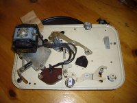
According to the attached photo, There are two ac windings on the TA motor.
It would make sense that each winding sees the added resistance. You will have to inspect the wiring to determine the most efficient way of doing this. 1kΩ may be a suitable starting point. Bear in mind that I have no direct experience of doing this, only what I have garnered from the link I provided.
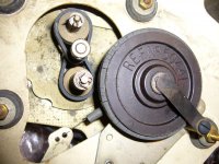
If the rubber of the idler or jockey wheel has become hard and brittle, it will transmit vibrations from the motor to the platter. Check this first.
I have linked to a pdf of the TA MkII user instructions which give details re voltage ratings etc.
https://www.radio-workshop.co.uk/service/Garrard-Model-TA-MK%20II-Turntable%20.pdf
According to the attached photo, There are two ac windings on the TA motor.
It would make sense that each winding sees the added resistance. You will have to inspect the wiring to determine the most efficient way of doing this. 1kΩ may be a suitable starting point. Bear in mind that I have no direct experience of doing this, only what I have garnered from the link I provided.
If the rubber of the idler or jockey wheel has become hard and brittle, it will transmit vibrations from the motor to the platter. Check this first.
I have linked to a pdf of the TA MkII user instructions which give details re voltage ratings etc.
https://www.radio-workshop.co.uk/service/Garrard-Model-TA-MK%20II-Turntable%20.pdf
Attachments
Last edited:
- Home
- Source & Line
- Analogue Source
- AC Motor Vibration