I am on my way to design an all dc coupled 300b se amp. I study the material from valvewizard and would like to seek your guidance in drawing the ac loadline for dc coupled stage and the calculation of output impedance.
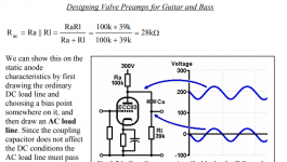
Q1. For drawing the AC loadline,the first pic has clearly explained the calculation of R(ac), which only involve the load resistor and the grid resistor of the next stage. But how about dc coupled stages? I learned from quite a number of dc coupled design and noted that there is no grid resistor in the next stage. So is that the R(ac) is approx. just equal to the load resistor resistance ?
Q2. The second pic shown the output impedance calculation, which involve the load resistor and plate resistance. Does the output impedance affect the frequency response of the next stage through the miller capacitance? For dc coupled stages where there is no grid leak resistor, does the impedance to be involved in calculating the frequency response just equal to the output impedance of the first stage? So for AC coupled stages when grid leak resistor exist in the second stage, does the impedance involved equal to output impedance of first stage in parallel with the grid leak resistor of the second stage (plus grid stopper resistance in series in there is any)?
Attachments

Last edited:
1) A valves grid has a Z of a few meg, use 1m as a rough guide for your calcs,but the best way is to test in the actual circuit.
2) Look up the inter electrode C for your valve, for a triode it's larger than a pentode,then multiply by the gain of the stage,that together with the IP Z will form a high pass filter and effect F response. The Miller effect means you might need a hefty driver stage to overcome it. I calculate Z for LF and HF, take the worst case and select a driver to suit.Or you can just forget about it and always use a hefty driver in all your amps, I use this approach. I don't bother with many calculations prefering to use a driver with highish current and low OP Z every time, in most cases this works fine.
Regarding F response if your using direct coupled and only one stage you can pretty much forget about it: F response and stability will be good.
Andy.
The 300B grid to plate capacitance is 15pF.
The 300B mu (u) is 3.85.
The 300B plate resistance, rp, is 700 Ohms.
A 300B amp with a 3500 Ohm primary output transformer has a gain of 3.2
3.85 (3500/(3500 + 700) = 3.2
The plate to grid capacitance plus miller effect capacitance is (1 + 3.2) x 15pF = 63pF.
Careful:
You are designing a 300B direct coupled amplifier.
Pay attention to the power up sequence, so that the 300B grid voltage will not cause unusually high plate current, or unusually high grid current, or both.
That will destroy the expen$ive 300B.
Last edited:
How the frequency response be affected by Miller capacitance? Is that only by the low pass filter formed by the grid stopper / the volume pot resistance (the portion that is in series to the input of tube), and nothing in relation to the output source impedance from previous stage/ grid leak resistor (as they are in parallel to the Miller capacitance)?
Last edited:
All of the Resistances, including the plate resistance, rp, of a stage that drives them, and all of the Capacitances determine the high frequency response of that area.
The preamp output impedance, the potentiometer setting (the position changes the high frequency response), grid stopper, and input miller effect C all affect the high frequency at that location of parts in the amp.
If the preamp to power amp input is -1 dB at 20kHz due to the potentiometer setting and Rs and Cs including the miller effect C; Then if the driver rp and 300B C and miller effect C is -1 dB at 20kHz; and then if the 300B plate resistance and output transformer distributed C (and the leakage reactance from primary to secondary) are -1 dB at 20kHz . . .
Then the total high frequency response will be -3dB at 20kHz.
I hope that explains it.
Last edited: