Hi people,
Instead of using Ltspice I am practicing drawing loadlines to get some better understanding. I got a bit stuck with the AC load at 20000 Hz of the design attached.
The DC load must be 101.82 K.
AC load at 20000 Hz in my eyes is 2.79 K in parallel with 470K = 2.78K
Is this correct or does the 220r resistor comes into play because the signal is tapped above it?
Kind regards and thank you.
Attachments
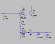
The 220r has signal so must be driven, yes. Part of the reason for the 100k:220r divider is to pad-out annoyances like 2800pFd of line capacitance.
You realize this plan will clip around a tenth of a volt? A very low line level. Not an impressive guitar level. Do you really need that much division? For hundred foot cables, a 1k impedance is fine.
You realize this plan will clip around a tenth of a volt? A very low line level. Not an impressive guitar level. Do you really need that much division? For hundred foot cables, a 1k impedance is fine.
Thanks PRR.
So the AC load line at 20kHz would be at 101.82 || 2.78K || 470K || 220r? AC load at 20KhZ = 203 Ohms?
You mean it will clip at 0.1V output right?
I am aiming for -20 dBu output, about 0.22V p-p without clipping and lowest thd I can manage.
So the AC load line at 20kHz would be at 101.82 || 2.78K || 470K || 220r? AC load at 20KhZ = 203 Ohms?
You mean it will clip at 0.1V output right?
I am aiming for -20 dBu output, about 0.22V p-p without clipping and lowest thd I can manage.
You mean AC load as seen by the tube? If so, no. The 2.78k is only in parallel with the 220R and 470K resistors. It is not in parallel with R4 or R6 (1.6k/100k).So the AC load line at 20kHz would be at 101.82 || 2.78K || 470K || 220r? AC load at 20KhZ = 203 Ohms?
The load seen by the cathode is therefore roughly 100k from the external resistor, in parallel with the internal resistance of the triode itself.
If you're only considering the external load, then it's roughly 100k. No need to worry about the 220R and friends.
Yes, the external 220R // 470k // 2.78k adds on to the 100k resistor. But 220R is roughly five hundred times smaller than 100k; its effect on the cathode load is less than one quarter of one percent. Therefore, it is completely irrelevant. (Your tube has at least +/- 10% variation in its own parameters, and you're probably using 5% resistors. It makes no sense to worry about 0.25% somewhere else.)
PRR is saying (in a less direct way): Throw away the 220 ohm resistor. Replace it with 1k. You will get more output voltage, and no worsening in performance. 🙂I am aiming for -20 dBu output, about 0.22V p-p without clipping and lowest thd I can manage.
-Gnobuddy
Thanks PRR and Gnobuddy. The question is purely for being able to draw the ac load line. The actual design is just to play with.
I thought that in order to draw it, I first have to make the dc load line and mark the bias point. For instance 300V, 101.82K = mark 300v 0 mA and 0v 2.95 mA. Draw line. Choose bias point. Draw mock up AC load line. ( For this I am trying to figure out the load resistance in parallel with the DC resistance, hence my question). Keep slope of AC load line and draw it so it intersects with the bias point.
Is this technique ok? So Gnobuddy, the AC load is 2.78 || 220R || 470K. But for drawing the ac load line as described above this will also be parallel to the 101.82 K right?
Kind regards
I don't think so, Jim....the AC load is 2.78 || 220R || 470K. But for drawing the ac load line as described above this will also be parallel to the 101.82 K right?
The load line shows you what the active device (here, the triode) "sees". In this case, the cathode of the triode "sees" the 1.6k resistor, in series with 100k, first. That is already a load of 101.6 k.
The parallel combination of (2.78k, 220R, 470k) is about 204 ohms. This extra 204 ohms is in series with 101.6k (not in parallel with it), and will add on to it, raising it to 101.8k.
In this case, the DC and AC loads are almost exactly identical; the only difference is the added 470k in parallel with the 220R for AC. Since 470k is so much bigger than 220R, this will have hardly any effect at all.
-Gnobuddy
@jan.didden : 10uF is output capacitor. The 2850pF is cable capacitance. 470K is input impedance of next stage.
Thanks Gnobuddy, I finally got it. Thank you for taking the time.
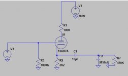
As far as cathode followers I am starting to like the one shown below. The gain seems to be very low, which is not a problem, but its about 0.55, is this correct?
What I like is that on startup when the output capacitor isn't charged, the dc output voltage will be divided by the 100K/2K2 voltage divider, right? DC elevation is also not needed.
When I change the 2K2 to for example 10K, I get more gain, about 0.82.
If I want to do 0.22V peak to peak either will do it, which one is preferable? Looking for transparancy and low DC output at startup.
Thanks Gnobuddy, I finally got it. Thank you for taking the time.
As far as cathode followers I am starting to like the one shown below. The gain seems to be very low, which is not a problem, but its about 0.55, is this correct?
What I like is that on startup when the output capacitor isn't charged, the dc output voltage will be divided by the 100K/2K2 voltage divider, right? DC elevation is also not needed.
When I change the 2K2 to for example 10K, I get more gain, about 0.82.
If I want to do 0.22V peak to peak either will do it, which one is preferable? Looking for transparancy and low DC output at startup.
Attachments
Did you take that from Merlin Blencowe's book? (Designing Valve Preamps for Guitar and Bass)As far as cathode followers I am starting to like the one shown below.
It's an excellent book, with a lot of very useful information in it.
In the circuit you posted, note the anode load (100k), which doesn't exist in a cathode follower. This particular circuit is more than an emitter follower: you get an amplified, inverted signal at the anode, and simultaneously, a somewhat attenuated, non-inverted, lower-impedance signal at the cathode.
I haven't done the math, but that sounds about right.The gain seems to be very low, which is not a problem, but its about 0.55, is this correct?
If you're curious about these things, why not start teaching yourself how to use LTSpice? It is freeware, and you can use it to simulate circuits and answer questions like these.
That's not how this circuit works. Note the way the grid is connected straight to ground (0 volts)?...the dc output voltage will be divided by the 100K/2K2 voltage divider, right?
That means the cathode will bias itself a few volts positive (around 1.5 volts for a half-12AX7). There is no high voltage there at all, so there is no need to divide anything down.
True, because the cathode is only at +1.5 volts or so. 🙂DC elevation is also not needed.
The 100k resistor is doing nothing for you if you only care about the cathode signal. You can remove the 100k and connect the anode (aka plate) straight to B+.
True enough. "Less loss" may be a more accurate way to put it than "more gain", since both are less than unity! 😀When I change the 2K2 to for example 10K, I get more gain, about 0.82.
There is not much change in DC turn-on voltage whether you use 10k or 2.2k. It will be slightly more with the 10k resistor, but probably not enough to make any significant difference. With a half-12AX7 in the circuit you showed, the cathode will never end up more than about 3.5 volts positive, no matter what value of cathode resistor you use....which one is preferable? Looking for transparency and low DC output at startup.
If you really want transparency, the truth is that any high-voltage MOSFET (source follower) will beat the pants off a vacuum triode cathode follower...and MOSFETs are better at driving low-impedance or high-capacitance loads, too. They are also cheaper, smaller, don't get hot, less fragile, and will last for your lifetime.
For transparency and low output impedance, any op-amp will beat the pants off the MOSFET, too. But that's another story. 🙂
Since you're posting to the "Instruments And Amps" forum, I assume you are interested in tube guitar amplifiers. What makes tubes good for guitars is not their transparency, but the exact opposite: tubes have severe flaws, but those flaws happen to complement the flaws in the electric guitar sound, and the combination of flawed instrument + flawed tubes can produce excellent sounds.
Solid-state devices are much better than tubes at being truly transparent. But when you put a solid-body electric guitar through a truly transparent amplifier, the amplifier reveals the harsh, ugly, cold, sterile sound of the instrument. Very few people actually like that sound.
An analogy: if you want to apply paint uniformly to a surface, a paint roller is a much better tool than a paint brush. A paint brush has many flaws: it can only cover a small width at a time, it can only produce a rather short stroke before running out of paint, the paint stroke is not uniformly dense, it leaves behind brush strokes, et cetera.
But if you are an artist, which tool do you use to paint your masterpiece? The near-perfect paint roller, or the much more flawed paint-brush?
It turns out that the flaws in the paint-brush are the very thing that makes it a better tool for a painter. Brush strokes, non-uniform colour application, narrow coverage, these are all the things that make it possible to create fine art with a brush. Nobody creates great paintings with a paint-roller.
-Gnobuddy

That's not how this circuit works.JimvdB said:
...the dc output voltage will be divided by the 100K/2K2 voltage divider, right?
Right; and yet there is a scrap of truth here. And you should not need SPICE to see it. The "pointless" 100K in the plate is reflected-down to cathode divided by Mu, or about 1K Ohms. Also the triode's ~~60k plate resistance, for another 600r; total 1.6k. And 1.6k divided by the 2.2k cathode resistor probably does make a 1:0.55 divider, near enough.
And as you say: nearly no headroom because the grid is not lifted. It is like my Corgi's belly: low-slung, drags on tall grass. If you WANT distortion, this is one way. But I thought this was an FX send? Don't combine dirty and clean functions in one stage without divine inspiration and months of gig-testing.
IIRC, Merlin Blencowe suggests this circuit as one way to avoid wasting an entire triode just to buffer an FX-send output. He also suggests that the limited headroom is a good thing, as it will keep you from accidentally destroying guitar effects pedals....The "pointless" 100K in the plate...
(In context, he discusses some badly designed commercial tube guitar amp FX-send schematics that can accidentally send tens of volts of signal to a guitar FX pedal.)
I kinda mentioned the (Rp/mu) thing in an earlier post in this thread, in the context of AC load line. I think it might be too subtle an idea for this thread, so I dropped it.
Nice analogy!It is like my Corgi's belly: low-slung, drags on tall grass.
Many years ago, I was standing by a patch of ordinary lawn-grass at Venice Beach, California. A woman came along, with a squirrel-sized dog pattering along behind her on a leash, two-inch-long legs working like crazy. She strode from asphalt to grass, paying no attention to the dog, who bogged down, tripped, fell over, and was dragged through what was shoulder-high grass to it. 😱
That was the first time I had seen a dog quite that small. Seeing it helpless to negotiate an ordinary patch of short, level, mowed grass, I could not help but think what an atrocity we humans had committed, starting with powerful and intelligent wolves, and moulding them into helpless, half-witted cartoon-show toys by selective breeding.
-Gnobuddy
Thanks Gnobuddy and PRR!
I will have to take some time to digest all this. As a matter of fact, I did took this from Merlin Blencowe's book. I cherish this book. Although I know most of it by heart I still have a lot to do to understand it all.
I do use LTSpice and I have come to the conclusion that this schematic will not give the necessary headroom.
But ... drop a 12AU7 in there and watch it do 4.4V P-P with a THD of 0.5%. Any objections to this change and schematic?
Now about that 100K, and whether or not it is pointless. I was under the impression that at startup, with hot heaters, the tube is a dead short. That is why I thought there would be a 100K/2K2 voltage divider. I thought the 100K made this circuit have the low DC output at startup. This is not the case?
Lower parts count with same performance sounds better to me, if I can remove it I will.
at startup, with hot heaters
Did you leave the heaters hot all night? Usually the heaters are stone cold at startup. And the not-hot tube is a great insulator.
Transmitting tubes are often proportioned such that toward the end of warm-up the current is too much for the half-hot cathode. But that is why we use "receiving tubes"; these are proportioned for non-technical users, your grandparents.
Same here. A wonderful book, and exactly what I needed at the time, as I had zero background with tubes (but I knew solid-state analogue electronics quite well.)...Merlin Blencowe's book. I cherish this book...
A caution: there is a whopper of a mistake in Blencowe's book, in the section on calculating the output impedance of cathodyne phase splitters. That aside, the rest of the book is a goldmine.
The triodes in a 12AX7 are high Ra (anode currents are always small, never more than 3 mA). Transconductance is pretty high for a triode. So it only takes a few volts between grid and cathode to completely shut off that already-small anode current. With the grid tied to ground, that means there isn't a whole lot of headroom for a signal at the cathode.I do use LTSpice and I have come to the conclusion that this schematic will not give the necessary headroom.
Yes, lower Ra (aka Rp), so more anode current to start with, and it takes more grid-cathode volts to turn it off. Ergo, higher Vgk when biased to a reasonable operating point, and more headroom at the cathode.But ... drop a 12AU7 in there and watch it do 4.4V P-P with a THD of 0.5%. Any objections to this change and schematic?
With a 12AU7, you will almost certainly want to revisit the 100k anode resistor...either remove it entirely, or reduce its value to accommodate the higher anode current of the 12AU7.
For giggles, try plugging an LND150 (MOSFET) in place of the triode, in your LTSpice simulation. (LTSpice model attached, in case you need it.)
The LND150 will plug straight in where the half-12AX7 used to go. In real life, parameter spreads for the LND150 are wider than for the "toob", and operating point not as predictable - adjust on test often needed.
PRR already addressed the question of heaters being cold at start up (which means, no anode current, and therefore zero DC voltage at the cathode, until the heaters warm up.)I was under the impression that at startup, with hot heaters, the tube is a dead short.
Now let's look at the "dead short" idea a bit more closely. If you look at the 12AX7 datasheet (which is plotted with hot heaters), you will see that currents are not that big even with Vgk=0. For instance, when there is 100 volts between anode and cathode (Vak), and zero volts between grid and cathode (Vgk=0), anode current is barely 2 milli amperes.
If you then plug in ohms law (R = E/I), you'll notice the tube has a resistance of (100 volts/2 mA), or 50,000 ohms! Not a dead short by any means, though about as low as you'll get from this particular triode.
That's why this particular triode is said to have a high plate resistance Rp (aka high anode resistance Ra). Nothing you can do to it (without melting it) will make it flow more than about 3 mA. Nothing you can do to it will lower the anode-cathode resistance much below about 50k. (Unless you bias Vgk positive, a situation you are unlikely to encounter in any traditional 12AX7 circuit.)
Triodes with lower Ra than a half-12AX7 will flow a bit more current. But fundamentally, triodes are not very good at flowing lots of current. They never come anywhere close to being a "dead short". At best, they tend to be a big, fat, power-wasting resistor instead.
This is why triodes are so useless at power amplification. Which, in turn, is why pentodes (and beam tetrodes) very quickly replaced power triodes, even in the golden era of tube electronics.
Except for the unfortunate victims of the 300B "Single Ended Triode" cult, that situation hasn't changed in many decades.
Contrast that 50 kilo ohm Rp of the half-12AX7 with today's crop of power MOSFETs, many of which will indeed turn into a dead short, with source-drain resistances dropping to a few thousandths of an ohm when the MOSFET is turned fully on.
-Gnobuddy
Attachments
- Home
- Live Sound
- Instruments and Amps
- AC load line of split load cathode follower