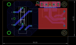
I'm drawing up a small board for the Recom RAC10-12DK AC-DC converter. It can be made very compact, even with IEC input, fuse and output filter onboard. But to achieve that, I've to run the output tracks under the converter. Do I risk picking up radiated noise or are these little boxes shielded well enough ?
So, back to the drawing board or not ? 😉
So, back to the drawing board or not ? 😉
Attachments
These units are normally potted in the box so that the underside may not be shielded at all. Just use topside groundplane underneath it? I think you are already doing this.
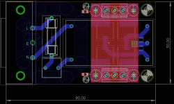
Thanks for the answer. Yes, I have a topside gnd plane right now and the power lines running under it. The big squares are smd shielded inductors. Normally, I would populate either the left or the right side, it gives me more flexibility.
I guess my question should be: is it ok to use that topside gnd plane for the gnd output or should it be used only as shield ?
I guess my question should be: is it ok to use that topside gnd plane for the gnd output or should it be used only as shield ?
Can you route the ground to the terminals on the back side of the PCB, then it will be shielded by the topside ground plane itself, making the converter ground output a star-point.