If I want to AC couple my input, which, I am told I should do, is this calculation correct? At each input, I have a 22.1K to ground, so I believe with a 1uF cap, this would give me a 7Hz HP,
1/(2*PI*22.1K*1E-6). Is this right and is this a low enough break? Thanks for any inputs. -bg
1/(2*PI*22.1K*1E-6). Is this right and is this a low enough break? Thanks for any inputs. -bg
Your calculation is correct. You should choose the frequency to be at least five times below the lowest frequency you can hear. The reference designs use 1 µF with a 47 k Rin, which gives 3,4 Hz and should even be sufficient for the 16 Hz the big church organ can do. With 22,1 k that would be 2,2 µF or bigger.
Take into account that AC coupled means you also need a capacitor in the feedback loop leg to ground. The frequencies should be matched or both frequencies should be sufficiently low, if unmatched.
Take into account that AC coupled means you also need a capacitor in the feedback loop leg to ground. The frequencies should be matched or both frequencies should be sufficiently low, if unmatched.
PBlue, thanks again for you inputs.Take into account that AC coupled means you also need a capacitor in the feedback loop leg to ground.
Since the fb is same at 22.1K, I should also put same uf in parallel with the 680 to ground in the schematic in this link? -bg
schematic
for Zin=22k1 or 22k I would recommend that a 3u9F or 4uF blocking cap be used at the input. This gives a High Pass input filter of F-1dB~3.5Hz & F-3dB~1.9Hz.
This requires the NFB blocking cap to be >= 1.414 * 22k1 / 680r * 3u9F >= 179uF. Use 220uF in series with the 680r.
With this value of NFB cap you can go upto 4u7F for an input blocking cap.
But to get the full benefit of this low frequency ability the series combination of the DC blocking cap in the source output and the DC blocking cap in the amp input must be ~4u7F.
If both pieces of equipment have a DC blocking cap and one of them is too small then arrange to short out the smaller cap. And ensure the one you keep is the highest quality that you think gives you good value.
Not sure what this means. I may be connecting this to any number of commercial equipment and would have not knowledge of any of this. Am I all wet here? I thought the reason for doing this would be to filter any DC caused by different ground potential between equipment. thx. -bgBut to get the full benefit of this low frequency ability the series combination of the DC blocking cap in the source output and the DC blocking cap in the amp input must be ~4u7F. If both pieces of equipment have a DC blocking cap and one of them is too small then arrange to short out the smaller cap. And ensure the one you keep is the highest quality that you think gives you good value.
Bypass Cap
Could I bypass an electrolytic with a 1uF poly?his requires the NFB blocking cap to be >= 1.414 * 22k1 / 680r * 3u9F >= 179uF. Use 220uF in series with the 680r.
Re: Bypass Cap
Once you have the soldering iron in your hands, you might just as well disable redundant filters or adapt them to get the best out of them. Of course you have to find out, if your taste is the same as Andrew's. And to find that out, you will have to try it out.
Yes, it is to filter DC. Usually those filters are present in all components. The trouble with them is that they add up to each other. And not all manufacturers have the same idea about the ideal roll-off frequency. So sometimes the filters are designed in a way that they can degrade the sound more than necessary.rgrayton said:I thought the reason for doing this would be to filter any DC caused by different ground potential between equipment.
Once you have the soldering iron in your hands, you might just as well disable redundant filters or adapt them to get the best out of them. Of course you have to find out, if your taste is the same as Andrew's. And to find that out, you will have to try it out.
Yes. It is even recommendable with the poly having around 1 % of the electrlytic's value as a rule of thumb.rgrayton said:
Could I bypass an electrolytic with a 1uF poly?
pacificblue
Thanks PBlue. I still don't get what the FB cap is all about or how it relates, but that is just my ignorance with this stuff. -bg
Thanks PBlue. I still don't get what the FB cap is all about or how it relates, but that is just my ignorance with this stuff. -bg
I may be connecting this to any number of commercial equipment and would have not knowledge of any of this.
hello.
perhaps you can build in two inputs - one with a cap ,.and the other without a coupling cap(used for preamps that got one).......
greetings............
hello.
perhaps you can build in two inputs - one with a cap ,.and the other without a coupling cap(used for preamps that got one).......
greetings............
Re: pacificblue
The amplifier has a DC offset that would otherwise be amplified with the same gain as the rest of the signal. If you take e. g. the worst case from the datasheet, i. e. 10 mV offset, amplify that with the gain of 33,5 from your post above you get 335 mV. That is already 0,014 mW of DC for the speaker, only 18,5 dB below 1 W. Sounds little, but being DC it takes little power to cook a voice coil, because the cooling effect of movement is missing at DC.
There were commercial amplifiers with a switch for that (Sansui?). So you could choose AC coupled or DC coupled operation. But as you said, you wouldn't know, if your other equipment allows DC coupled operation. So you would have two options. Try it and risk your speakers during the trial. Or open the other components up and look inside. One thing is for sure. DC coupled sounds better. But destroyed speakers are a high price for that.
The cap in the feedback leg to ground is there to guarantee unity gain for DC. A capacitors resistance increases with decreasing frequency. So the gain will decrease with decreasing frequency, because Ri + Ci will increase, while Rf stays the same.rgrayton said:Thanks PBlue. I still don't get what the FB cap is all about or how it relates, but that is just my ignorance with this stuff. -bg
The amplifier has a DC offset that would otherwise be amplified with the same gain as the rest of the signal. If you take e. g. the worst case from the datasheet, i. e. 10 mV offset, amplify that with the gain of 33,5 from your post above you get 335 mV. That is already 0,014 mW of DC for the speaker, only 18,5 dB below 1 W. Sounds little, but being DC it takes little power to cook a voice coil, because the cooling effect of movement is missing at DC.
mjf said:I may be connecting this to any number of commercial equipment and would have not knowledge of any of this.
hello.
perhaps you can build in two inputs - one with a cap ,.and the other without a coupling cap(used for preamps that got one).......
greetings............
There were commercial amplifiers with a switch for that (Sansui?). So you could choose AC coupled or DC coupled operation. But as you said, you wouldn't know, if your other equipment allows DC coupled operation. So you would have two options. Try it and risk your speakers during the trial. Or open the other components up and look inside. One thing is for sure. DC coupled sounds better. But destroyed speakers are a high price for that.

AndrewT,
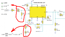
Hmm, here is scheme from CA 340a:
It uses 10uF cap + 22k resistor on input and 47uF cap + 1k res on NFB:
F=0.7hz
1.414*22k/1k*10uF = 311uF. Far from 47uF... If would be good to change these cap to ~310uf?
And the second variant:
Place 4.7uF input cap:
F=2.19hz
1.414*22k/1k*3.3uF = 100uF (2*47uf pana FC)
Thanks.
AndrewT said:for Zin=22k1 or 22k I would recommend that a 3u9F or 4uF blocking cap be used at the input. This gives a High Pass input filter of F-1dB~3.5Hz & F-3dB~1.9Hz.
This requires the NFB blocking cap to be >= 1.414 * 22k1 / 680r * 3u9F >= 179uF. Use 220uF in series with the 680r.
With this value of NFB cap you can go upto 4u7F for an input blocking cap.
Hmm, here is scheme from CA 340a:
It uses 10uF cap + 22k resistor on input and 47uF cap + 1k res on NFB:
F=0.7hz
1.414*22k/1k*10uF = 311uF. Far from 47uF... If would be good to change these cap to ~310uf?
And the second variant:
Place 4.7uF input cap:
F=2.19hz
1.414*22k/1k*3.3uF = 100uF (2*47uf pana FC)
Thanks.
Attachments
Hello!
I'm just interested, what voltage rating should have feedback cap? Datasheet says 50V, but I can't understand why so high... Maybe someone can explain?
Thanks.
I'm just interested, what voltage rating should have feedback cap? Datasheet says 50V, but I can't understand why so high... Maybe someone can explain?
Thanks.
Hi,
there should never be a significant AC voltage across the negative feedback capacitor during normal operation.
If the input filter is correctly sized then the AC voltage will ALWAYS be very low.
However if the input DC blocking cap is omitted, or far too high in value, then significant DC and LF AC voltage can appear across the capacitor. This voltage is limited by the attenuator action of the two feedback resistors.
If the amplifier goes faulty, then you can get either rail voltage across the capacitor. That will probably blow the front end as well as risk damage to the DC blocking capacitor.
There's solutions. Choose to accept the risk of failure, or limit the voltage using diodes or specify a high voltage bi-polar capacitor, But the front end will still blow up if the latter is chosen.
Thank You.
I'm Using 47uF\16V Pana FC now. And when I saw 50V in datasheet I was a bit worried 🙂
Next time I'll place there 50V just for safe...
P.s. And one more little offtopic question :
What for RC from output to GND (R56, C2 on pic above) is used?
And what type will be better for C2? (In stock it is simple ceramique. I swap that to Epcos MKT...)
R56 + C2 are half of the Thiele Network on the output.
This gives the amplifier a load to help stabilise it.
C2=MKT is OK.
Most recommend a high voltage for this capacitor. Use at least 100V and maybe as high as 250V.
This gives the amplifier a load to help stabilise it.
C2=MKT is OK.
Most recommend a high voltage for this capacitor. Use at least 100V and maybe as high as 250V.
.
Most recommend a high voltage for this capacitor. Use at least 100V and maybe as high as 250V. [/B]
Sorry for bringing this thread up again, but .. why is that. Why 100V+ ? Do we want to provide for the possibility of someone putting rail voltage across the inputs or what? Or it's something related to the internal properties of the cap on higher voltage ratings?
- Status
- Not open for further replies.
- Home
- Amplifiers
- Chip Amps
- AC Couple Input Value?