Hi everyone
My question is very simple,
It is correct to simulate a SS diode full bridge rectifier, followed by a CLC filtering, get the desired B+, and then convert to the "cockeyed bridge" topology, while expecting the same Vout and current capability?
Thanks in advance
J
My question is very simple,
It is correct to simulate a SS diode full bridge rectifier, followed by a CLC filtering, get the desired B+, and then convert to the "cockeyed bridge" topology, while expecting the same Vout and current capability?
Thanks in advance
J
Attachments
I mean ,of course, the same ratings, but with the added benefits of reduced SS diode glitches in both directions: to the Xformer windings and at the filter out
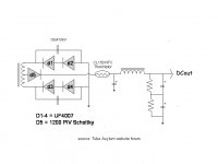
D5 is serving no useful purpose and can be removed, (unless blocking dc on the secondary winding when power is removed is a big deal?) otherwise it is identical in operation to the more conventional format. This doesn't IMHO confer any real or theoretical advantages over the more conventional approach as far as I can see. Just a different way of doing the same thing.
Last edited:
Thanks Kevin. The claim is "where the new rectification scheme will help is in reducing the amount of SS switching noise that gets into the power trafo and, via filament windings, into the signal path."
I was concerned about the problem of modelling the PSU as if it where a normal bridge rectifier in PSU designer II. Re thinking the whole thing , It seems to me that this is effectively the case. But you need a center tapped Xformer..
Probably under 400VDC you can use only two UF4007 and one Schottky..
Last edited:
Thanks Kevin. The claim is "where the new rectification scheme will help is in reducing the amount of SS switching noise that gets into the power trafo and, via filament windings, into the signal path."
I was concerned about the problem of modelling the PSU as if it where a normal bridge rectifier in PSU designer II. Re thinking the whole thing , It seems to me that this is effectively the case. But you need a center tapped Xformer..
Probably under 400VDC you can use only two UF4007 and one Schottky..
I can't see how it does that, it is after all electrically equivalent. The rectified current pulses along with any rectifier induced mis-behavior are still there in the high voltage secondary.
I'd focus on using fast, soft recovery diodes, proper snubbing, and if critical use a separate filament transformer. They cross contaminate each other anyway if dc filament supplies are in use.
Mmm .. probably the solution by Geek is the best (simple) option , when your Xformer is not center tapped..
(post 4 and 8)
http://www.diyaudio.com/forums/tubes-valves/117948-freds-psu.html
(post 4 and 8)
http://www.diyaudio.com/forums/tubes-valves/117948-freds-psu.html
Last edited:
Since I advocate the "cockeyed bridge", I (naturally) take exception to the thinking that the diode on the CT serves no useful purpose. Make that diode "noiseless", either Schottky or vacuum, and PN diode switching noise does not sneak into the B+ rail. Hop over to AA and search for VoltSecond's posts on the 5th diode in combination with a true bridge setup.
The OP asked about simulation. In fact, the "cockeyed bridge" is a FWCT setup and should be modeled as such.
In theory, the PIV rating of the "extra" diode is of no consequence, as reverse biasing never occurs. In practice, having a substantial PIV there is a good idea, as lots of things can go wrong. For instance, one fellow installed a Schottky backwards. Fortunately, he had a decent PIV part and it did not fail.
Thanks Eli, I'll search AAsylum for VS posts.
I will try different types of PSU's in a bredboard the following weeks. SS, tubes, Doublers, to gain practical experience in such a fundamental circuit part. Me and my friends, a huge Variac and a Fluke true RMS meter..
I will try different types of PSU's in a bredboard the following weeks. SS, tubes, Doublers, to gain practical experience in such a fundamental circuit part. Me and my friends, a huge Variac and a Fluke true RMS meter..
But what's special about the cockeye in particular? That extra, fast diode works the same with any rectifier configuration. Also, if you placed it in the ground side of the circuit then it wouldn't even need a high Vrrm rating.Since I advocate the "cockeyed bridge", I (naturally) take exception to the thinking that the diode on the CT serves no useful purpose.
For the two UF4007 diodes in series, wouldn't one want two shunt caps, one across each diode instead of one across both diodes?
D5 should never see any voltage greater than the output voltage, and it will only see that at the instant that power is turned off.
Shunt D5 with a cap of equal value to the two caps shunting the two diodes in series and it will only seee B+/3.
It's PIV rating can therefore be equal to B+/3, but is best kept at B+ or greater.
If D1-4 are already UF seried diodes, I don't see the advantage of an additional schottky in series with them.
If D5 being a Schottky would allow D1-4 to be 1N4007s instead of UF4007s, then I could see an advantage.
If D1 and D3 were 1200PIV SIC Schottky,
Those lesser diodes add nothing to the brew.
Common cathode being the more usual dual,
makes better sense to ground the center tap.
http://www.digikey.com/product-detail/en/C4D10120D/C4D10120D-ND/2679412
Those lesser diodes add nothing to the brew.
Common cathode being the more usual dual,
makes better sense to ground the center tap.
http://www.digikey.com/product-detail/en/C4D10120D/C4D10120D-ND/2679412
Last edited:
Eli's whole idea is to control the SS diode switching noise using just one special component, D5, rather than using the special (expensive) components for all of the diodes. This (diode switching noise) is a topic which could use a bit of fact to balance up the enormous amount of opinion floating around.
Guidance on SS Diode Switching noise - without (hopefully) getting too technical..
The diode junction (depletion region) has an electric field across it and hence has capacitance.
This junction capacitance has a Reverse Recovery charge (Qrr). That is, before a diode can turn off, this stored charge has to be removed or "swept out". Current has to flow to remove this charge. Therefore as the AC voltage reverses on a rectifier diode there will be a pulse of current in the wrong direction before the diode actually switches off. This puts a noise spike on the power supply rail which has very high current rate of change (di/dt). Filter capacitors are not very good at removing (shunting to ground) this noise spike because they have a small amount of inductance and inductors resist current change. Therefore you end up with a noise "SPLAT" on the power supply rail. The high di/dt also means that the noise spike can radiate and capacitively couple into damn near everything.
The differences in Silicon, Ultrafast Silicon, Schottky and Silicon Carbide Shottky of interest when using them as rectifiers is how fast they can turn off and how large this Current "SPLAT" is before turning off. This is obviously directly related to their Reverse Recovery Charge (Qrr). Small capacitors across each diode can help to absorb this splat and for some time they were in fact required by Electromagnetic Interference (EMI) standards for all commercial products (at least in Europe - I don't know if this is still true).
So here is the useful (representative ONLY) Qrr data:
Standard Silicon Diodes Qrr approx 500 nC (nano-Coulombs)
Ultrafast Silicon Diodes Qrr can be down to 100 nC
Schottky Diodes Qrr 50 to 70 nC
Silicon Carbide Schottky Diodes Qrr <20nC
The reverse current spike to turn OFF the "standard" diodes on each end of the centre tappped winding also have to flow through the "control" diode D5. So using something which turns OFF fast for D5 will prevent the much larger reverse current spike being generated. A tube ("hollowstate") diode for D5 will be even better as it simply does not allow ANY reverse current spike.
I can also attest to the fact that "bog standard" 1N4007 is just awful and generates a heap of switching noise. 1N5408 are even worse. Neither has any place in an audio amp, not even a guitar amp. At a minimum use the ultrafast versions UF4007, UF4508. Putting 10nF ceramic caps across the diodes can help OR for critcal designs use something like this idea from Eli to help manage the switching noise.
Remeber its always better to treat the disease than the symptom. That is, don't generate the noise in the first place rather than try to clean up the mess afterward.
Cheers,
Ian
In addition to the capacitive effect Ian described, another phenomenon occurs with PN junction diodes that adds to the switching noise. That phenomenon is minority carrier injection. When a PN junction is forward biased, "holes" get injected into the N region and electrons get injected into the P region. When the junction becomes reverse biased, the minority charge carriers get swept up and that adds to the reverse recovery spike.
A Schottky diode has only 1 "flavor" of semiconductor. There are no minority carriers to cause switching noise.
BTW, minority carrier injection can be a good thing. The phenomenon is what allows BJTs to work.
A Schottky diode has only 1 "flavor" of semiconductor. There are no minority carriers to cause switching noise.
BTW, minority carrier injection can be a good thing. The phenomenon is what allows BJTs to work.
shotties are up to 100,,200V max
Please check:
LXA20T600 Power Integrations | 596-1357-5-ND | DigiKey
And with silicone carbide, you get much more than that.
Forget DigiKey, unless they truly are the only game in town. Cree high PIV Schottky diodes can be sourced from Mouser. 😉 Mouser catalog page.
- Status
- Not open for further replies.
- Home
- Amplifiers
- Tubes / Valves
- AbouT the PSU II simulator & the "Cockeyed Bridge"